


Watt Amplifier Circuit:Types,Principle and Applications
Description for 150 Watt Amplifier Circuit
Amplifiers are one of the most commonly used circuits or devices in electronics. They are fundamental building blocks in wireless communication, broadcasting, and other audio systems, used to enhance the characteristics of a signal. An amplifier can be defined as an electronic device that increases the input signal. It boosts the voltage, current, or power of the input signal.
150 Watt Power Amplifier Circuit
Before discussing the concept of the 150W power amplifier circuit, it's essential to understand the types of amplifiers, power amplifier circuits, and the working principle of power amplifiers.
Types of Amplifiers
Amplifiers are categorized into two main types: weak-signal amplifiers and power amplifiers.
Weak Signal Amplifier
Weak signal amplifiers are used in wireless receivers, acoustic pickups, audio tape players, and CD players. These amplifiers are designed to handle small input signals and must generate minimal internal noise while significantly increasing the signal voltage. Field Effect Transistors (FET) are particularly efficient for such applications.
Power Amplifier
Power amplifiers are used in broadcast transmitters, wireless transmitters, and high-end audio systems. These applications typically use bipolar transistors. The primary considerations in power amplifications are power output and efficiency.
Power Amplifier Circuit
A power amplifier circuit is designed to drive loads, such as speakers, with minimal output impedance. Speakers require high power at low impedance. In this design, the amplifier circuit uses a push-pull class AB configuration to achieve the necessary power amplification.
The principle behind designing an amplifier circuit lies in the various ways of biasing a Bipolar Junction Transistor (BJT). The electrical signal output from the microphone is typically low. To amplify this low voltage signal to a sustainable level, the Common Emitter (CE) configuration of a BJT is used, biased in class A mode. In this mode, the output is an inverted amplified signal with low power. To further amplify the power level of this signal, two Darlington power transistors are arranged in a class AB configuration. A transistor configured in class A mode drives this transistor configuration.
Concept of Power Amplifier Circuit
The main aspects of the circuit are the class AB amplifier and a class A voltage amplifier. A transistor biased in class AB mode produces an amplified output signal for one half of the input signal. Thus, a class AB amplifier consists of two transistors, where one conducts for one half of the input signal and the other conducts for the second half. In practice, a class AB amplifier uses diodes to bias the two transistors and eliminate crossover distortion. A transistor biased in class A mode produces an inverted input signal but has low efficiency.
Working of the Power Amplifier
Power amplifiers are designed differently to meet various requirements of 20W, 50W, and 100W RMS values. A power amplifier circuit is uniquely designed to produce voltage and power gain and consists of three amplification stages:
- Voltage amplification stage
- Driver stage
- Output stage
These stages work together to amplify the input signal to the desired power level.
The following circuit diagram discusses the 150W power amplifier circuit.
This circuit uses TIP 142 and TIP 147 in a Darlington combination to deliver 150W RMS to a 4Ω speaker. These complementary Darlington pair transistors can handle 5A current and 100V voltage.
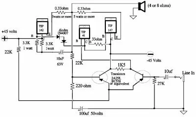
Two BC 558 transistors, Q5 and Q4, are wired as a pre-amplifier, and TIP 142 and TIP 147, together with TIP41, are used for driving the speaker. This circuit is powered by a 5A dual power supply.
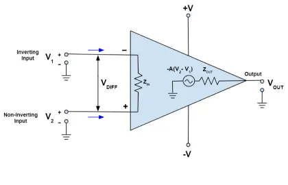
The pre-amplifier section of this circuit is based around transistors Q4 and Q5, which form a differential amplifier. A differential amplifier reduces noise and provides a means for applying negative feedback, thereby improving the overall performance of the circuit. The input signal is applied to the base of Q4 from the junction of a 0.33Ω resistor and a 22KΩ resistor. A complementary class AB push-pull stage is built around Q1 and Q2 to drive the speaker. Diodes D1 and D2 bias the complementary pair and ensure proper class AB operation. Transistor Q3 drives the push-pull pair, with its base directly coupled to the collector of transistor Q5.
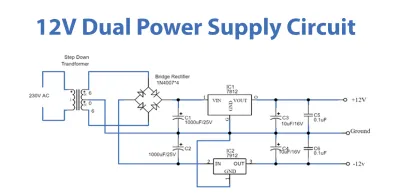
A +40V/-40V unregulated dual supply powers this amplifier circuit. This power supply is sufficient for powering one channel. For stereo applications, the current ratings of the transformer, diodes, and fuses should be doubled. The circuit diagram below illustrates the dual power supply unit.
Applications of Power Amplifier Circuit:
- - Used to drive a speaker with low input impedance.
- - Used to drive high power antennas for long-range transmission.
Drawbacks:
- - The use of BJTs causes more power dissipation, reducing the system's efficiency.
This article covers the concepts of power amplifier circuits, their types, and their working. Hopefully, it provides a better understanding of this topic.
Related Articles
Difference Btween Amplifier and Current-Sense Amplifier
What is TL074 Operational Amplifier?
Voltage Amplifier vs Power Amplifier: What’s the Differences?
Push-pull Amplifier :Overview and Working Principle


