


Linear vs Switching Battery Charger IC Comparison
Introduction to Battery Charger IC Architectures
Battery charger integrated circuits are small power management units that are used to charge rechargeable batteries in a controlled manner with respect to voltage and current profile. The contemporary lithium battery systems typically make use of the CC-CV (constant current-constant voltage) charging algorithms that provide the safety, battery life, and energy efficiency. Electronic design has two prevailing charger architectures: linear battery charger ICs and switching battery charger ICs. Although they both achieve the same aim of charging, their working principles, behaviour of efficiency, thermal and complexity of the system differ vastly, and it is thus worthy to make sure that the correct option of either is taken when working with portable electronics, embedded systems and industrial battery-driven devices. The knowledge of such differences will help the engineer to make the most out of the loss of power and thermal and PCB design in choosing the most suitable charging solution.
How Linear Battery Charger ICs Work
A linear battery charger IC regulates charging current by operating a pass transistor in its linear region, effectively behaving like a controllable resistor between the input supply and the battery. The constant-current phase and constant-voltage phase keep the current flowing through the charging device and the voltage drop constant, respectively, by continuously adjusting the voltage drop. Due to the lack of any high-frequency switching, linear chargers produce very low levels of electrical noise and need very few external components, which makes them well-suited to very compact layouts and sensitive analog systems. Nonetheless, the non-utilized energy between the input voltage and the battery voltage is lost as heat within the IC; that is, efficiency is directly proportional to the voltage difference and the level of charging current. The RT9525GQW devices are one example of common linear charger designs that are optimized based on the requirement to have simple USB-powered charging designs where circuit simplicity and costs are more important than efficiency.
How Switching Battery Charger ICs Work
Switching battery charger ICs use high-frequency DC-DC conversion, typically based on buck converter topology, to step down input voltage efficiently before delivering energy to the battery. Instead of dissipating excess voltage as heat, switching regulators transfer energy through inductors and switching transistors, significantly improving power conversion efficiency. This architecture allows higher charging currents while maintaining lower thermal stress, which is especially important in modern portable electronics and fast-charging systems. Switching chargers adds other external devices like inductors, capacitors and compensation networks to the design, making them more complex to design and sensitive to PCB layout, although they save energy levels by a factor of 100 and enhance thermal considerations. An example of a switching-based charger IC that is meant to deliver a higher efficiency in high loads than conventional linear chargers is the RT9527GQW.
Efficiency Comparison: Linear vs Switching Charger IC
Efficiency is the most important differentiator between linear and switching battery charger ICs. Linear chargers theoretically achieve efficiency equal to the ratio of battery voltage to input voltage, meaning significant power loss occurs when charging from higher supply rails, such as 5 V USB sources, into lower-voltage lithium cells. The lost energy converts directly into heat, limiting the allowable charging current. In contrast, switching charger ICs regulate energy transfer through pulse-width modulation, often achieving efficiency levels above 85–95% depending on load conditions and component selection. As charging current increases, switching solutions maintain stable efficiency while linear devices experience exponential thermal stress. Switching chargers, therefore, are used where high power or high rate charging is needed and linear chargers in low current designs where simplicity has more importance than the efficiency requirements.
Thermal Performance and Power Dissipation Analysis
Direct impacts of thermal behaviour are on the reliability of chargers, battery safety and user experience. Linear charger ICs dissipate the product of voltage drop and charging current, which can rapidly heat junctions in small devices unless it is properly heat-spread. The charging time may be increased due to thermal regulation systems within the IC, which tend to lessen the current charging automatically due to overheating. Switching charger ICs will share the power loss in switching elements and magnetic parts, which can minimize the temperature increase considerably inside. Although switching devices introduce switching losses and electromagnetic noise considerations, overall thermal efficiency remains superior, enabling higher sustained charging currents and improved long-term system stability. Proper thermal design, therefore, becomes a deciding factor when comparing linear and switching charging architectures.
PCB Design Complexity and External Component Requirements
Linear charger ICs provide a low-implementation complexity design, in design terms, since they need only the input/output capacitors and a small number of resistors in design. This simplicity reduces PCB space requirements and speeds development cycles, making linear chargers attractive for entry-level consumer electronics and ultra-compact devices. Switching charger ICs, however, require careful PCB layout to control switching noise, minimize loop area, and maintain stable regulation performance. Inductor selection, compensation network tuning, and grounding strategy all influence efficiency and electromagnetic interference behaviour. Although the switching designs require more engineering work, they offer scalability and performance benefits that are required in the current high-efficiency power systems.
RT9527GQW vs RT9525GQW Battery Charger IC Comparison
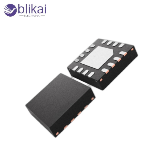
The RT9527GQW and RT9525GQW chargers depict the practical implementation of the difference between switching and linear charging methods. The RT9525GQW focuses on simplified linear charging architecture, offering low external component count, low noise operation, and straightforward implementation suitable for low-power USB-powered devices or cost-sensitive designs. Its primary weakness is thermal dissipation in situations where input voltage is much higher than battery voltage, which limits the charging current in high-power conditions. Instead, the RT9527GQW uses a switching-based charging system, which increases the efficiency of conversion and minimizes heat production, allowing higher currents to be charged and making it much more suitable for performance-related portable electronics. The engineers who alternate between such devices are forced to strike a balance between the efficiency goals, thermal limits, PCB complexity, and the overall system cost instead of working with electrical specifications alone.
|
Feature / Parameter |
RT9525GQW (Linear Charger) |
RT9527GQW (Switching Charger) |
|
Architecture |
Linear |
Switching (Buck Converter) |
|
Charging Efficiency |
Moderate (losses as heat) |
High (85–95% typical) |
|
Thermal Performance |
Higher heat dissipation, thermal limiting |
Lower heat, better thermal stability |
|
Charging Current Capability |
Limited by input-battery voltage difference |
Supports higher charging currents |
|
External Components |
Minimal (capacitors, resistors) |
More components required (inductor, capacitors, compensation network) |
|
EMI / Noise |
Very low, suitable for noise-sensitive circuits |
Higher EMI, requires careful PCB layout |
|
Application Suitability |
USB-powered low-power devices, compact designs |
Fast-charging devices, smartphones, industrial battery modules |
|
Complexity |
Simple design, easy to implement |
More complex, requires careful design and layout |
|
Cost |
Lower |
Slightly higher due to extra components |
Application Scenarios: Choosing the Right Charger Type
Linear battery charger ICs are typically used in wearables, small IoT sensors, and low-capacity battery systems, where charging current is typically small, and electromagnetic noise needs to be kept to a minimum. The charging ICs used should be switching chargers, where the efficiency and thermal stability of the switching charger directly influence the usability of the product, because it is in smartphones, handheld instruments, industrial battery modules, and fast-charging portable systems. The use of switching architectures is becoming more popular as device power density is ever getting smaller, but in systems with an ultra-low power requirement or with space constraints, a linear solution is still acceptable.
How to Choose Between Linear and Switching Battery Charger ICs
Selecting between linear and switching battery charger ICs requires evaluating system-level priorities, including efficiency targets, thermal limits, available PCB area, electromagnetic compatibility requirements, and expected charging speed. Linear chargers can be used by designers with small power budgets or small layouts because of their simplicity and predictable operation, and designs with big power requirements, low heat generation, and fast charge cycles can use switching charger designs. Charger profiles, input power sources and enclosure thermal capability should be reviewed to be able to find the best charger in accordance with product performance objectives.
Conclusion
Linear and switching battery charger ICs each serve essential roles in modern electronic power design, and neither architecture universally replaces the other. Linear chargers are simple, produce low noise, and need few components; thus are suitable in low power applications, whereas switching chargers are efficient and thermal in high-current charging conditions. The comparison between RT9525GQW and RT9527GQW demonstrates how architectural differences translate directly into real-world design tradeoffs. Knowing the efficiency behaviour, thermal properties, and the complex aspects of the system, engineers can choose the most suitable battery charging system and attain effective and efficient power management in the current electronic products.
FAQ
What is the difference between linear and switching battery charger ICs?
Linear chargers are easy, non-noisy and dissipate surplus voltage as heat, whereas switching chargers are more efficient, generate less heat, but need more components.
Can a linear charger IC overheat?
Yes, when the input voltage is greater than the battery voltage, a heat sink is produced, slowing the speed of charging.
Are switching chargers noisier than linear chargers?
Yes, switching chargers produces high-frequency noise; linear chargers are quieter.
Some images are sourced online. Please contact us for removal if any copyright concerns arise.


