


Circuit Board Repair: Guide for Beginners
What is a Circuit Board?
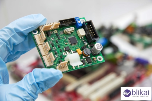
A circuit board, in a stricter sense, refers to a flat plate that holds and connects various electronic components using conductive paths, pads, and other features. Together with high conducting paths, it provides support for electrical circuit assemblies. They are found in devices ranging from low-tech gadgets to high-arcing machine tools.
Types of Circuit Boards
1. Printed Circuit Board (PCB): The most common type, it involves mounting electrical components like resistors, capacitors, and integrated circuits (ICs) onto an insulation board such as fiberglass or composite material and interconnecting via copper traces that have been etched directly onto it.
2. Flexible Circuit Board: Said boards can be bent and folded under unusual or crowded shapes due to their construction from bendable materials, like polyimide. Consequently, they are particularly suited for applications such as wearable devices and flexible displays, where space constraints apply.
3. Double-sided PCB: These circuit boards are distinguished by conductive layers on both sides thereof, permitting their factors to be mounted and connected on either side.
4. Multi-layer PCB: Multi-layer circuit boards are used in surroundings where there's a need for lower vestiges; they've numerous layers of PCB material erected, one on top of the other, each performing as its circuit.
Components Mounted on a Circuit Board
- Resistors
- Capacitors
- Inductors
- Transistors
- Integrated Circuits (ICs)
- Connectors and switches
Function
Circuit boards are essential for:
- Providing mechanical support for the components.
- Allowing electrical connections between components using copper traces.
- Ensuring signals and power are routed correctly between components.
Common Causes of Circuit Board Damage
Physical Damage
One of the primary reasons for circuit board failures is circuit board damage from physical sources, whether during manufacturing, assembly, or normal use. Defects like cracks, scrapes, or chips to the face of a circuit board can beget breaks in conductive paths, resulting in signal loss or overall circuit board failure. For illustration, cracks or breaks in the circuit board face can ramify connections between factors, rendering them inoperable. Also, broken factors, similar to resistors or capacitors, can be affected by improper running or dropping the board, leading to circuit failure. Ensuring proper handling, storage, and protection during manufacturing and maintenance is crucial to prevent these types of physical damage.
Electrical Issues
Short circuits and power harpoons are two common electrical problems that can lead to serious consequences for a circuit board. A short circuit, which is when a live current comes into contact with the ground through an unintended pathway, can lead to overheating and element damage. Also, power surges — harpoons in voltage beyond the board's capacity — can beget breakdowns in the separating accouterments and destroy factors. Proper grounding, insulation, and voltage regulation are essential preventive measures against electrical issues that could otherwise compromise circuit boards.
Environmental Factors
Moisture and corrosion can be major sources of circuit board damage in humid or corrosive environments. Moisture percolating through can beget short circuits as it degrades material dielectric parcels, leading to electrical failure, while erosion due to moisture or swab exposure erodes essence corridors on the board, corroding factors and connections. Over time, this compromises functionality and lifetime compromising functionality and lifetime, reducing its functionality and lifetime significantly, taking defensive coatings and enclosures to be installed around circuit boards in order to alleviate its environmental exposure and ensure dependable operation and lifetime of functionality and lifetime.
Tools Required for Circuit Board Repair
- Soldering iron and soldering materials
- Multimeter for testing circuits
- Desoldering pump and braid
- Magnifying glass or microscope
- Safety gear (gloves, goggles)
Step-by-Step Circuit Board Repair Process
- Step 1: Identify and diagnose the problem
- Step 2: Power off the device and prepare the work area
- Step 3: Inspect the circuit board for visible damage
- Step 4: Remove faulty components
- Step 5: Clean the board and surrounding areas
- Step 6: Solder in new components
- Step 7: Test the repaired board
Common Circuit Board Repair Techniques
Soldering Basics
Mastering soldering is foundational for circuit board repair. It involves heating solder to connect electronic components securely. This process involves melting solder to bond electronic components together. A good solder joint ensures conductivity and a strong mechanical bond. Proper soldering tools and techniques can help to prevent damaging delicate parts, keeping the board working properly for years to come.
Surface-Mount Component Replacement
Replacing surface-mount components requires skill and precision. These tiny factors are soldered directly onto the PCB face. In order to replace these factors, you need a lot of skill and delicate touch with a good brace of tweezers and a heat gun to avoid damaging the girding factors and traces.
Reflow Soldering for Complex Repairs
Reflow soldering is ideal for complex repairs involving multiple pins or intricate components. It uses controlled heat to melt solder paste, allowing simultaneous bonding of multiple contacts. This technique is commonly used for repairing high-density PCBs, ensuring uniform and strong connections across all components.
Wire Jumper Technique
The wire jumper technique is useful for bypassing damaged PCB traces. A thin wire connects two points, restoring the circuit's pathway without replacing the entire trace. This method is practical for minor repairs and troubleshooting, allowing quick fixes while maintaining overall board functionality.
Troubleshooting Circuit Board Problems
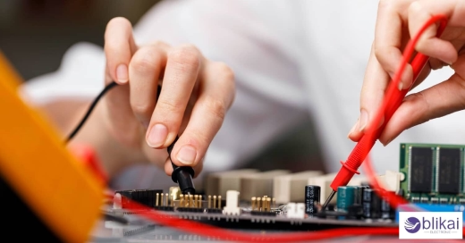
Using a Multimeter for Continuity Testing
A multimeter is essential for checking circuit continuity. This test ensures connections between components are intact, detecting open circuits or breaks in traces. Using this test, you can snappily single out connections that don't allow electricity to inflow and diagnose your circuit.
Identifying Faulty Capacitors, Resistors, and Diodes
In a lot of cases, circuit boards fail because of a non operating element, generally a capacitor, resistor, or diode. Visually examining for becks or bulges and using a multimeter to measure capacitance, resistance, or diode function helps identify issues, ensuring these factors operate within specified parameters.
Checking Power Supply and Voltage Regulators
Verifying the power supply and voltage regulators is crucial in troubleshooting. Anomalies in voltage output often indicate issues with regulators or power sources. Measuring input and output voltages with a multimeter helps confirm the stability and accuracy of the power supply, preventing further board malfunctions.
Tips for Circuit Board Repair
Work in a Static-Free Environment
Static electricity can damage sensitive circuit components. Working in an ESD-safe environment using wrist straps and mats protects components from unintended electrical discharge, thus maintaining circuit integrity during repairs.
Handle Components Carefully
Circuit board components can easily be damaged through excessive force or careless handling, so use tools such as tweezers and ESD-safe pliers when handling components carefully to avoid damaging any connections or cracking fragile parts during repairs.
Take Your Time and Avoid Rushing
Rushing repairs increases the risk of mistakes, like poor solder joints or misaligned components. Taking time to double-check connections and placements ensures quality work, improving repair success and preventing the need for future rework.
Conclusion
In conclusion, successful circuit board repair combines technical skills, proper tools, and a careful approach. By mastering techniques like soldering, continuity testing, and component handling, you can tackle common issues confidently. Focus on detail and adherence to best practices help ensure repairs remain functional over time - keeping electronic systems functional as long as possible!
Final Thoughts
Conducting effective circuit board repair takes patience, precision, and an acute attention to detail. Adherence to best practices--working in an ESD-safe environment using suitable tools--ensures reliable results. Troubleshooting skills and careful handling of components minimize damage risks. With practice, these techniques improve repair success and prolong circuit board life.
Related Articles
Types of Circuit Breakers: Overview and Applications
Discrete Circuit vs Integrated Circuits: What's the Differences?
Best FHP100N07 Replacement MOSFETs for High-Performance Circuits
Microprocessor vs Integrated Circuit:Which One Is Better
What is an Integrated Circuit (IC)? Working, and Types (Guide)


