


Air Circuit Breaker:Features, Specification and Applications
A circuit breaker is an electrical apparatus designed to interrupt a circuit either manually or remotely under normal operating conditions. Its primary purpose is to disrupt a circuit in the event of faults such as short circuits or over-currents. Typically, a circuit breaker serves to switch or safeguard the system. Other devices like relays, switches, and fuses are also employed for similar purposes. Circuit breakers find applications mainly in power systems and industrial settings to safeguard and regulate various components within the circuit, including transformers, switch gears, motors, alternators, generators, etc. Various types of circuit breakers are utilized in industries, with the air circuit breaker being one such type. This article provides an overview of the air circuit breaker.
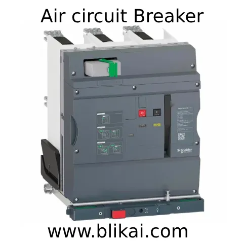
Air Circuit Breaker: What Is It?
An electrical device called an air circuit breaker (Air Circuit Breaker) is used to safeguard electric circuits with currents ranging from 800 amps to 10 000 amps from overcurrent and short circuit. Typically, these are employed in low voltage settings (less than 450V). These systems are located in Distribution Panels (below 450V). We shall talk about how an air circuit breaker operates in this article.
A circuit operation breaker that functions in the air as an arc extinguishing medium at a specific atmospheric pressure is known as an air circuit breaker. Present-day air circuit breakers and switching gears come in a variety of forms and are easy to install, operate well, and last a long time. Oil circuit breakers have entirely been superseded by air circuit breakers.
Construction of Air Circuit Breakers
A variety of internal and external components, such as the following, can be used to make an air circuit breaker.
The Air Circuit Breaker's external components primarily consist of the ON/OFF button, a position indicator for the main contact, an energy storage mechanism indicator, LED indicators, a RST button, a controller, a rated nameplate, an energy storage handle, displays, a shaker, a fault trip rest button, a rocker repository, and more.
The main internal components of the Air Circuit Breaker are the steel-sheet supporting structure, the insulating box for the pole group, the current transformer that protects the trip unit, the horizontal terminals, the arcing chamber, the terminal box, the closing springs, the CB opening and closing control, the plates that move the main and arcing contacts, and the plates that are fixed.
Operational Principle of Air Circuit Breakers
The operational principle of the air circuit breaker differs from that of other types of CBs. It's known that the primary function of a CB is to extinguish arcing and prevent its reestablishment, where the gap between contacts withstands the system's recovery voltage.
The air circuit breaker operates similarly but with a unique approach. During arc interruption, it generates an arc voltage instead of relying solely on the supply voltage. This arc voltage is defined as the minimum voltage required to sustain the arc. The circuit breaker can enhance the supply voltage in three distinct ways:
Cooling the arc plasma can increase the arc voltage.
By breaking the arc into multiple segments, the arc voltage can be raised.
Increasing the length of the arc path also increases the arc voltage, as the resistance along the path grows, leading to a higher voltage drop across the arc path.
The operating voltage range extends up to 1KV. It comprises two sets of contacts: one primary pair made of copper, which carries the current, and another pair made of carbon. Upon opening the circuit breaker, the primary contacts disengage first, while the arc contacts remain connected. Once the arc contacts separate, arcing commences. The circuit breaker is obsolete for medium voltage applications.
Air Circuit Breaker Operation
Air circuit breakers function with their contacts exposed to the surrounding air. Their approach to controlling arc quenching differs entirely from that of oil circuit breakers. Typically employed for low-voltage interruptions, air circuit breakers are increasingly replacing high-voltage oil breakers. The schematic below elucidates the operating principle of an air circuit breaker.
Air circuit breakers generally feature two sets of contacts: the primary contacts (1) carry current under normal load conditions and are crafted from copper, while the secondary contacts (2), known as arcing contacts, are composed of carbon. Upon the circuit breaker opening, the primary contacts disengage first, leaving the arcing contacts still in contact with each other.
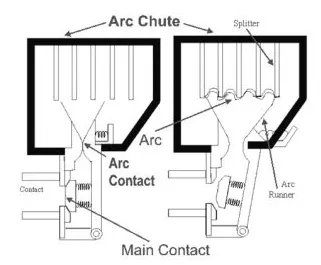
As the current finds a low-resistance path through the arcing contacts, no arcing occurs in the primary contacts during their opening. Arcing only initiates when the arcing contacts are ultimately separated. Each arcing contact is equipped with an arc runner to aid in this process.
The arc discharge ascends due to both thermal and electromagnetic effects. As depicted in the figure, the arc moves into the arc chute, lined with splitters. Within the chute, the arc cools, elongates, and splits, causing the arc voltage to exceed the system voltage. Consequently, the arc is extinguished during the subsequent current zero.
The air circuit breaker enclosure, constructed from insulating and fire-resistant material, is partitioned into sections by barriers of the same material. At the bottom of each barrier lies a small metal conductor bridging the gap between its adjacent sides. As the arc ascends, it is segmented by these barriers, yet the metal conductors maintain electrical continuity between the arcs in each section, placing the arcs in series.
Within each section of the chute, electromagnetic forces induce the arc to form a helical shape. All these helices are connected in series, significantly elongating the arc length and increasing its resistance, thereby reducing the current in the circuit.
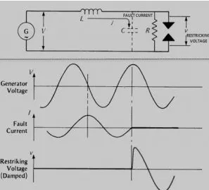
The arc's trajectory from leaving the main contacts to entering the arc chute is illustrated in Figure (a). Upon current cessation at zero, ionized air within the arc's path acts as a shunt resistance across the open contacts and the self-capacitance C, as depicted in the figure. This high-resistance path dampens the oscillation between C and L in the circuit, effectively preventing re-striking of the arc.
The waveform depicted below illustrates the absence of high-frequency oscillations due to the heavy damping effect, leading to the rapid rise of the restriking voltage to its peak generator voltage value.
Variants of Air Break Circuit Breakers
Air circuit breakers come in four primary types, widely utilized for indoor medium-voltage maintenance and household switch gears.
- Plain Break Type Air Circuit Breaker or Cross-Blast Air Circuit Breaker
- Magnetic Blowout Type Air Circuit Breaker
- Air Chute Air Break Circuit Breaker
- Air Blast Circuit Breaker
- Plain Break Type Air Break Circuit Breaker
Plain break air circuit breakers represent the most basic form of air breakers. Their primary contacts are configured as two horns, between which the arc extends. This type is also referred to as cross-blast Air Circuit Breaker. Typically, these circuit breakers incorporate a chamber, known as an arc chute, surrounding the contacts.
The arc chute facilitates cooling and is composed of refractory material. Internally, the arc chute features walls and is divided into smaller compartments by metallic separation plates, which act as arc splitters. Each compartment serves as a mini-arc chute, dividing the initial arc into a sequence of arcs, thereby increasing arc voltages compared to the system voltage. Plain break type Air Circuit Breakers are employed in low voltage applications.
Magnetic Blowout Type Air Break Circuit Breaker
Magnetic blowout air circuit breakers are designed for voltage capacities up to 11KV. These breakers utilize the magnetic field generated by current flow in blowout coils to extend the arc.
By exerting magnetic control over the arc movement, these breakers facilitate arc extinction. The blowout coils, connected in series within the disrupted circuit, induce a magnetic field that redirects the arc into arc chutes. Here, the arc is cooled and elongated. While the magnetic field doesn't directly manage the arc, it guides its movement to facilitate cooling and extension. Magnetic blowout type Air Circuit Breakers are commonly used up to 11kV.
Air Chute Air Break Circuit Breaker
The air chute air break circuit breaker utilizes copper main contacts to conduct current when in closed positions. Known for their low contact resistance, these main contacts are typically silver plated. In contrast, the arcing contacts are crafted from a solid, heat-resistant copper alloy.
This type of circuit breaker features two distinct types of contacts: main and arcing (or auxiliary). Main contacts, constructed from copper or silver-plated plates, offer reduced resistance and efficiently conduct current when the breaker is closed. On the other hand, arcing or auxiliary contacts are fabricated from copper alloy for their ability to withstand high temperatures.
The inclusion of arcing or auxiliary contacts serves to protect the main contacts from damage caused by arcing, and they can be easily replaced when necessary. During operation, both sets of contacts are opened and closed before and after the main contacts in the circuit breaker.
Air Blast Circuit Breaker
Air blast circuit breakers are employed in systems with voltages ranging from 245 KV to 420 KV, and sometimes even higher, especially in scenarios requiring swift breaker operation. Compared to oil-based counterparts, this type of circuit breaker offers several advantages:
- Elimination of fire hazard risk.
- Consistently high breaking speed throughout operation.
- Rapid arc quenching during breaker operation.
- Uniform arc duration across all current disruptions.
- Reduced heat generation from arc to contacts due to shorter arc duration, resulting in extended contact service life.
- Maintenance of system stability, which relies on the breaker's operational speed.
- Lower maintenance requirements compared to oil circuit breakers.
- Air blast circuit breakers come in three main types: axial blast, axial blast with sliding moving contact, and cross blast.
Maintenance of Air Circuit Breakers
Air circuit breakers serve as essential circuit protection devices for a wide range of low-voltage applications, up to 600V AC, including UPS systems, generators, mini power stations, MCCB distribution boards, etc. Their capacities typically range from 400A to 6300A, or larger.
Approximately 20% of failures in power distribution systems are attributed to inadequate maintenance, characterized by tough grease, dust accumulation, corrosion, and frozen components. Therefore, regular maintenance is crucial to ensure consistent operation and prolong the breaker's lifespan.
Proper maintenance of air circuit breakers involves several steps. First, the breaker should be switched off and isolated by opening the necessary electrical isolators. Subsequently, the breaker should be operated in this isolated state to check for any issues in restricted and distant areas on an annual basis. Following this electrical check, the breaker should be mechanically operated while still in a restricted state. This comprehensive process helps maintain the breaker's reliability by removing any surface layers that may have developed between sliding surfaces.
Air Circuit Breaker Testing Procedure
Testing of circuit breakers is essential to verify the operation of each switching system and the functionality of the entire tripping mechanism. It plays a crucial role in ensuring the safety and reliability of circuit breakers, which can be more challenging to test compared to other devices.
Malfunctions in circuit breakers can lead to various issues such as short circuits in coils, incorrect behavior, or damage to mechanical connections. Regular testing is necessary to detect and rectify these faults.
Various types of tests are conducted on circuit breakers, including mechanical, thermal, dielectric, and short circuit tests. Routine tests include trip tests, insulation resistance tests, connection tests, contact resistance tests, overload tripping tests, and instantaneous magnetic tripping tests.
Testing Methods and Equipment
Circuit breaker testing involves the use of different types of test equipment to evaluate the condition of the circuit breaker within a power system. Testing can be performed using various methods and equipment, such as analyzers, micro ohmmeters, and primary injection testers with high current capabilities.
Benefits of Circuit Breaker Testing
Circuit breaker testing offers several benefits:
- Enhanced performance of the circuit breaker
- Ability to check the circuit on load or offload conditions
- Identification of maintenance requirements
- Prevention of issues
- Early detection of faults
- Advantages of Air Circuit Breakers
Air circuit breakers offer several advantages, including:
- High-speed reclosure capability
- Suitability for frequent operation
- Lower maintenance requirements
- High-speed operation
- Elimination of fire risk associated with oil circuit breakers
- Consistent and short arcing time, resulting in reduced contact burning
- Disadvantages of Air Circuit Breakers
Despite their advantages, air circuit breakers have some drawbacks:
- The arc chute principle is less efficient at low currents, where electromagnetic fields are weak.
- The efficiency of the arc chute diminishes at low currents, leading to slower arc movement and potential challenges in achieving high-speed interruption.
Applications of Air Circuit Breakers
Air circuit breakers find extensive applications in controlling power station auxiliaries and industrial plants. They provide protection to various electrical machines such as transformers, capacitors, and generators.
Primarily, air circuit breakers are deployed in plants where fire or explosion hazards are prevalent.
The air brake principle utilized in air breaker circuit arcs is applicable to both DC circuits and AC circuits up to 12KV.
Air circuit breakers possess high resistance power, aiding in the enhancement of arc resistance through splitting, cooling, and lengthening.
Air circuit breakers are integral to electricity sharing systems and NGD applications, especially at 15kV.
In summary
Air circuit breakers play vital roles in safeguarding industrial plants and electrical machinery, while also ensuring reliable operation in environments prone to fire or explosion risks. This comprehensive understanding of air circuit breakers is essential for efficient implementation in electrical and electronic projects. If you have any doubts or require assistance with such projects, please feel free to leave your feedback in the comment section below. Here's a question for you: What is the primary function of an Air Circuit Breaker?


