


Inductor Fundamentals: Definitions, Functions, Features, Types, and Parameters
In the design process of inductive circuits, we often only pay attention to the magnitude of inductance, but it is easy to overlook that the inductance value also varies with frequency; we may identify the DC resistance of an inductor, but we neglect to consider its characteristics regarding AC resistance. This article attempts to share some definitions, functions, characteristics, types, and key parameters of inductors that are commonly overlooked.
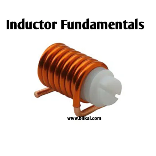
What is an Inductor?
An inductor is typically made up of coils wound around a solid material, which usually exhibits ferromagnetic or high permeability properties. In fact, the electromagnetic field is generated based on the internal windings and the direction of current flow in a specific manner.
Inductor Backlash Characteristics and Orientation
A key characteristic of inductors is backlash. The magnetic field generated internally and around the inductor stores energy and, in the event of a rapid power shutdown, releases energy onto the connected circuit at very high voltages.
As the voltage across the inductor decreases, the magnetic field undergoes decay and stores the energy required to produce the high voltages (critical for many circuit designs and could damage sensitive components). The coils inside the inductor always remain the same, regardless of whether they are flipped. When inverted, a coil rotating clockwise upwards will still rotate clockwise upwards. When observed from the top down, the rotation follows a clockwise direction. Conversely, if the coil is inverted, the rotation will be counterclockwise when viewed from top to bottom.
Regardless of the direction and orientation of the inductor winding, the polarization of the magnetic field is irrelevant to the backlash because the current induced by the voltage across the inductor in the connected circuit always flows in the opposite direction. This is why a single inductor has no polarity. The real issue lies in how to properly apply the current based on the desired circuit characteristics.
The Fundamental Functions of Inductors
Inductors primarily serve the following functions:
When current passes through them, they produce a magnetic field. Conversely, when the magnetic field fluctuates, current is induced.
This process involves converting electrical energy into magnetic energy and storing it.
Allowing the passage of direct current (DC) but impeding alternating current (AC), particularly at higher frequencies.
Functions (1) and (2) stem from the properties of electromagnetism, specifically electromagnetic induction. Function (3) concerns the DC and AC characteristics of inductors resulting from impedance. The following specific examples demonstrate the utilization of these properties.
(1)Generating a magnetic field when current flows through. Conversely, when the magnetic field changes, current flows. ⇒ Principle of Transformers
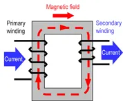
Principle of Transformers
The primary and secondary sides of this example structure have two winding wires, akin to a transformer. Passing current through the primary side winding wire generates a magnetic field, inducing current in the secondary side winding wire. This phenomenon, known as mutual inductance in transformers, facilitates voltage transformation based on the ratio of winding turns between the primary and secondary sides.
(2)Converting electrical energy into magnetic energy and storing. ⇒ Principle of Chokes
Principle of Chokes
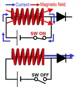
This is an example of an inductor in DC/DC converters. When current flows through the inductor due to switching on, it creates a magnetic field, which stores energy in the form of magnetic energy. When the current flow through the inductor is stopped by switching off, the stored magnetic energy is released (leading to a change in the magnetic field), thereby causing the flow of current.
(3) Allowing the flow of direct current while hindering alternating current, especially at higher frequencies. ⇒ Filtering Capability
Inductors can be integrated with capacitors to form low-pass, high-pass filters, and more. This exploits the inductor's property where impedance changes with frequency, influencing the flow of alternating current. Impedance characteristics will be described later.
Properties of Inductors
Perfect and Real Inductors (Impedance Attributes)
Perfect inductors exhibit only inductance without any losses in energy. On the other hand, actual inductors consist of resistance components (DC resistance: DCR) and capacitance (parasitic capacitance: Cp) in addition to inductance (as indicated in equivalent circuits). The resistance includes the resistance elements of wound wire and a core, while the capacitance primarily consists of the line capacitance of the wound wire.
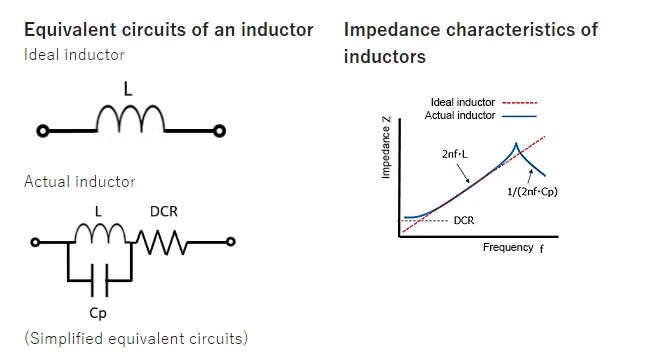
The illustration depicts a conceptual representation of impedance characteristics of ideal and actual inductors across different frequencies. In ideal inductors, impedance rises consistently as frequencies increase. Conversely, real inductors exhibit self-resonance caused by parasitic capacitance, resulting in decreased impedance at higher frequencies, potentially affecting their intended functionality. Additionally, losses occur due to resistance elements, contributing to impedance reductions.
Magnetic Saturation Characteristics
Inductors enter magnetic saturation when the current they carry exceeds the maximum allowable level for magnetic saturation, also referred to as the DC bias allowable current, causing a decrease in inductance. As described in the earlier mentioned impedance equation, saturated inductors show reduced impedance and encounter unusually high current flow. As a result, devices such as DC/DC converters may face decreased efficiency and operational challenges. The magnetic saturation allowable current serves as a crucial parameter in determining the behavior of inductors.
AC Resistance (ACR)
While the earlier discussion in the impedance section centered exclusively on DC resistance (DCR), real-world inductors also include resistance components that contribute to eddy current losses within the core and resistance from conductive wires that intensify due to skin and proximity effects. These components collectively form the AC resistance (ACR). AC resistance (ACR), which rises proportionally with frequency, has a significant effect on power losses and raises component temperature at high frequencies, requiring careful consideration in practical applications. (Subsequent explanations regarding eddy current losses, skin effects, and proximity effects will be provided.)
Additional Characteristics:
Q Factor (Quality Factor):
The Q factor, representing the ratio of inductive reactance to resistance at a specific frequency, serves as a performance metric for inductors. A higher Q factor indicates closer adherence to the behavior of an ideal inductor. It is calculated by dividing the inductive reactance (XL = ωL = 2πfL) by the AC resistance (ACR), quantifying losses concerning frequency. Notably, a high Q factor corresponds to a low ACR value according to the equation.
Copper Losses:
These losses stem from the resistance components encountered when current passes through a conductive wire.
Iron Losses
Losses occurring within a core due to the movement of magnetic flux, encompassing hysteresis and eddy current losses, are termed iron losses.
Skin Effect
With increased current frequency through a conductor, current tends to flow predominantly along the conductor's surface, leading to higher current density at the surface and, consequently, increased resistance—a phenomenon known as the skin effect.
Proximity Effect
When multiple conductive wires are close to each other, the magnetic field from each induces eddy currents in adjacent wires. At elevated frequencies, current becomes concentrated in areas where wires are in close proximity, resulting in heightened current density and resistance—a phenomenon known as the proximity effect.
Eddy Current Losses
Alterations in the magnetic field caused by electromagnetic induction trigger the generation of eddy currents within the core of a conductor. The energy carried by these currents transforms into heat owing to the resistance of the core material, leading to the occurrence of eddy current losses.
Hysteresis Losses
When altering or reversing a magnetic field within a core, it returns to its original state with hysteresis, as depicted by a hysteresis loop in BH diagrams of core materials. The energy consumed during this hysteresis action is lost as heat, known as hysteresis losses, which are proportional to the area of the hysteresis loop.
Primary Parameters of Inductors
The primary parameters of inductors are outlined as follows. While numerous attributes of inductors were elucidated in the preceding section, not all attributes are categorized as specifications. Presented here are the typical characteristics detailed in the datasheets of inductors.
Types of Inductors
Types by Form
- Fixed Inductors
- Variable Inductors
Types by Magnetic Material Properties:
- Air-Core Inductors
- Ferrite-Core Inductors
- Iron-Core Inductors
- Copper-Core Inductors
Types by Operating Characteristics:
- Antenna Coils
- Oscillating Coils
- Choke Coils
- Trap Coils
- Deflection Coils
Types by Inductor Function:
- Oscillating Inductors
- Correction Inductors
- Deflection Inductors for Cathode Ray Tubes (CRTs)
- Choke Inductors
- Filtering Inductors
- Isolation Inductors
- Compensation Inductors
Subcategories of Oscillating Inductors:
- Television Horizontal Oscillating Coils
- East-West Correction Coils
Deflection Inductors for Cathode Ray Tubes (CRTs):
- Horizontal Deflection Coils
- Vertical Deflection Coils
Choke Inductors (also known as Choke Coils):
- High-Frequency Choke Coils
- Low-Frequency Choke Coils
- Choke Coils for Electronic Ballasts
- Choke Coils for Television Horizontal Frequency
- Choke Coils for Television Vertical Frequency
Filtering Inductors:
- Power Supply (Mains Frequency) Filtering Inductors
- High-Frequency Filtering Inductors
Classification by Winding Structure:
- Single-Layer Coils
- Multi-Layer Coils
- Honeycomb Coils
Classification by Operating Frequency:
- High-Frequency Inductors
- Medium-Frequency Inductors
- Low-Frequency Inductors
Air-Core Inductors, Ferrite-Core Inductors, and Copper-Core Inductors are generally used as medium or high-frequency inductors, while Iron-Core Inductors are mostly used as low-frequency inductors.
Classification by Structural Features:
- Core-Coil Inductors
- Variable Inductors
- Color-Code Inductors
- Coreless Inductors
13. Inductors can be additionally classified according to their structural variances as wire-wound inductors and non-wire-wound inductors (including multi-layer chip inductors, printed inductors, etc.). They can also be segregated into fixed inductors and adjustable inductors.
Fixed inductors are further categorized into
- Air-Core Inductors
- Core Inductors
- Iron-Core Inductors
These can also be categorized based on their structural forms and pin arrangements as vertical same-axis pin inductors, horizontal axial pin inductors, large and medium-sized inductors, compact inductors, and chip inductors.
Adjustable inductors are further categorized into:
- Core Adjustable Inductors
- Copper-Core Adjustable Inductors
- Sliding Contact Adjustable Inductors
- Series Mutual Inductance Adjustable Inductors
- Multi-Tap Adjustable Inductors.
Easily Overlooked Inductor Parameters
Inductance Value and Frequency
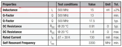
We'll take the example of the 744901115.
The datasheet specifies an inductance value of 15nH, with a tolerance of +/-2% achievable under testing conditions of 500MHz.
However, the inductance value is not constant and will vary with changes in frequency. If you want to know the inductance value at a specific frequency, you can refer to the inductance-frequency curve. This curve is typically provided in the datasheet.
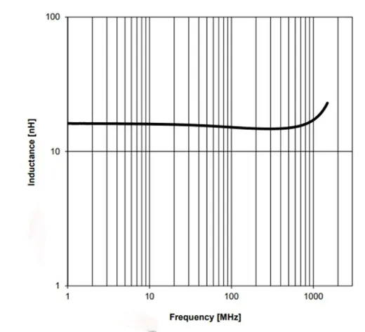
In general, it is crucial for the inductance-frequency curve to exhibit maximum flatness.
Impedance of an Inductor
Direct Current Resistance (DCR)
Direct Current Resistance (DCR) represents the resistance of an inductor when the signal frequency approaches 0Hz. Typically, common inductors have a low DCR value.
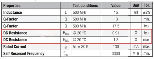
For example, taking the 744901115 as a reference, the DCR typical value at 20°C is 0.91Ω, with a maximum value of 1.8Ω.
When evaluating inductors with identical physical dimensions, the following tendencies usually apply:
- Higher inductance corresponds to higher direct current resistance (DCR).
- Lower inductance corresponds to lower direct current resistance (DCR).
It's worth emphasizing that DCR plays a critical role in determining wire heating losses. Hence, opting for a lower DCR whenever feasible is essential to minimize the power losses of the inductor.
Alternating Current Resistance (ACR)
Inductor specifications frequently incorporate the direct current resistance (DCR) but might omit alternating current resistance (ACR). However, in high-frequency scenarios, there might be a necessity to account for alternating current resistance.
.webp)
Real inductors contain resistance elements causing eddy current losses within the core and resistance from conductive wires that rise due to skin and proximity effects. These factors constitute the alternating current resistance (ACR). The ACR value rises proportionally with frequency (as illustrated in the example below), greatly impacting power losses and component temperature at elevated frequencies. Hence, it's crucial to account for real-world application scenarios.
Tip: Impedance Calculation for Inductors
Impedance can be understood as the degree to which passive components in an AC circuit reduce or impede current flow. This applies equally to high-frequency radio applications or high-frequency digital circuit applications because they all share the commonality of having some form of voltage variation in any periodic waveform. (Note: This is not limited to just sine waves.) Some DC waveforms can operate with steady DC inputs, including square waves, sawtooth waves, triangular waves, and other pulse patterns.
The following are equations for voltage and current across an inductor:
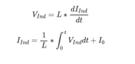
Inductor Power
Many inductor datasheets specify the rated current but do not specify the rated voltage and power. The rated current of the inductor is determined by the maximum current applied in the circuit design. To determine the maximum power the inductor can withstand before burning out, you can multiply the rated current by the voltage used in the circuit. To evaluate the power dissipation in the inductor resulting from resistance, you can input the direct current resistance (DCR) into the formula to assess if there are any notable losses.
Self-Resonant Frequency (SRF)
Due to the inherent capacitance in the winding structure of any coil, its self-inductance and distributed capacitance will resonate at a certain frequency, known as the self-resonant frequency (SRF).
At the self-resonant frequency, the inductor and its parasitic capacitance exhibit a resonant circuit with almost infinite high impedance.After surpassing the self-resonant frequency, the characteristics of the "inductor" mimic those of a capacitor.
In the diagram provided, the black line depicts the inductance value, whereas the red line illustrates the impedance value.
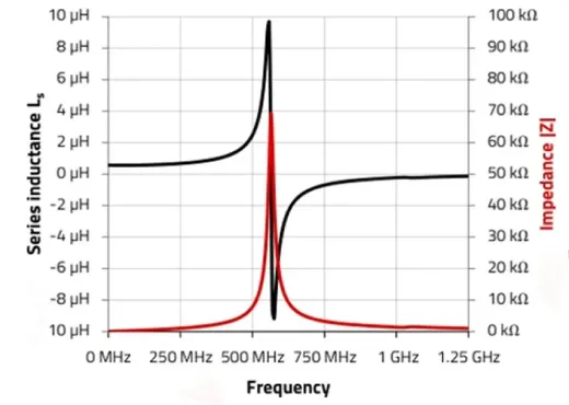
Yes, when designing high-frequency circuits, it's important to consider not only the inductance value but also ensure that the self-resonant frequency (SRF) is significantly higher than the operating frequency. This occurs because at or near the self-resonant frequency, the inductor may display unforeseen behaviors, potentially resulting in circuit performance deterioration or instability.Therefore, designers need to consult datasheets during component selection to understand the inductor's self-resonant frequency and ensure that the chosen inductor's SRF is significantly higher than the required operating frequency.
Related Articles
Inductor vs Resistor: What’s the Differences?
Understanding Coupled Inductors: Operations and Practical Applications
CBC3225T102KR Inductors: Features, Specifications, and Datasheet


