


Emergency Light : Diagram & Its Working
Emergency lighting is utilized in urgent situations, such as when the main power supply is disconnected or the regular electrical illumination fails. Sudden power loss could result in a fire or a blackout. This lighting system is employed in buildings and includes a battery to automatically activate the lights upon power failure. In emergency situations, these lights play a crucial role in providing safety for occupants. If a power outage occurs, an emergency light can activate using batteries to visually indicate a safe evacuation route for the residents to exit the building. This article provides an overview of emergency lights and their operation.
What is an Emergency Light & How it Works?
Definition: An emergency light is used to automatically illuminate a lamp powered by a battery. It prevents the user from being in a difficult situation due to unexpected darkness and helps the user access immediate emergency lighting. This circuit utilizes light-emitting diodes instead of incandescent lamps, making the circuit highly energy-efficient and producing brighter light output. Additionally, the circuit employs an innovative approach to enhance the cost-effective characteristics of the unit.
Emergency lights are connected to the building's electrical supply. Each light has its own circuit. These lights include a battery to serve as a backup power source when the building loses its main power supply. The battery's lifespan is relatively short compared to other lighting systems. Therefore, all emergency lights must be regularly checked to ensure the battery can provide emergency lighting for a minimum of 90 minutes. These tests are necessary to verify the battery's performance every six months with the help of professionals.
How do Emergency Lights Appear?
There are various types of lights available in the market, differing in size and shape. Each light is designed based on the specific application. Some common emergency lighting systems used in buildings are:
- Exit Lights
- Batten Lights
- Oyster Lights
- Spotfire Lights
How to Make an Emergency Light / DIY Emergency Light
The DIY emergency light can be constructed through a step-by-step process. The essential components of the 12V emergency light circuit diagram primarily include an LDR (Light-Dependent Resistor), 50K VR (Variable Resistor), 10K Resistor, BD139 and BD140 transistors, a 33-ohm resistor, a white LED, and a 12V battery.
Connect the circuit on the breadboard as per the diagram shown below using the components mentioned.
In this circuit, the LDR-based light will activate a high-watt white LED when the room is dark. It can be used as a simple lamp in a child's room to alleviate panic conditions during a power failure. This circuit provides adequate lighting in the room.
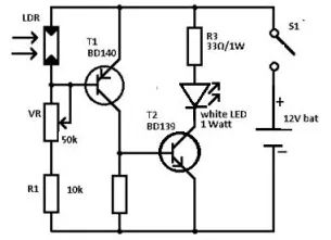
The design of this circuit is straightforward, allowing it to be assembled in a compact enclosure. A 12V small battery is used as the power source to supply the circuit. The transistors, T1 and T2, are employed as electronic switches to turn the white LEDs ON and OFF.
When there is sufficient light within the room, the LDR becomes active, causing the base terminal of transistor T1 to become high. The remaining transistor, T2, also turns off as its base terminal is grounded. In this condition, the white LED will turn off. Once the light falling on the LDR decreases, the T1 transistor, being forward-biased, will provide base current to transistor T2. This T2 transistor will then turn on, causing the white LED to illuminate.
Here, the LED is a 1-watt high-brightness Luxeon diode. It consumes approximately 300mA of current. Therefore, it is advisable to turn off the lamp to conserve battery power after a few minutes.
Emergency Light Circuit Diagram
An emergency light system is used to automatically illuminate a lamp when the regular AC supply stops working, and it turns OFF once the main power supply is restored.
This light is crucial where power outages occur frequently, as it can prevent the user from a challenging situation when the mains power supply unexpectedly fails. It allows the user to access an alternative, such as turning on an inverter or a generator, until the primary supply is reinstated.
Circuit Explanation & Working
Here, there are two circuits that operate using a 6V battery and a 12V battery. The construction of these circuits is shown below. These circuits can be built with LEDs instead of incandescent lamps, making them highly power-efficient and providing a clear, bright output.
6V Emergency Light Circuit Diagram
The circuit diagram of the 6V emergency light is shown below. The essential components of this circuit primarily include 10K and 470-ohm resistors, a 100uF/25V capacitor (C1), bridge diodes like D1, D2 (1N4007), D3 to D5 (1N5408), a BD140 transistor (T1), a 0-6V, 500mA transformer (Tr1), LEDs, and a switch (S1) with change-over contacts, powered by a 6V battery.
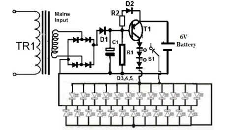
In the above circuit, a standard power supply primarily includes a transformer, a capacitor, and a bridge circuit. The key component used in this circuit is a PNP transistor. In this case, the transistor is utilized as a switch.
When the main supply is ON, the positive supply reaches the base terminal of the 'T1' transistor, causing it to be switched off.
Thus, the voltage from the battery is unable to reach the LED bank, keeping it switched off. Simultaneously, the battery is charged by the power supply voltage through a trickle charging system.
However, as soon as the main supply is interrupted, the positive voltage at the base terminal of the transistor will disappear, and it will be forward-biased through the 10K resistor.
If the transistor 'T1' turns ON, the LEDs will illuminate immediately. Initially, all the diodes are connected in the voltage line and gradually turn on one by one as the LED gets dimmer.
Applications of Emergency Light
The applications of these lights include the following:
Emergency lights are used where the illumination turns on automatically when the power supply is disrupted.
These are utilized as emergency lamps in buildings, homes, workplaces, and study rooms to mitigate the impact of unexpected power outages.
These lights are employed in various industries.
FAQs
1). What are the best emergency lightings?
Some popular options include Wipro coral, Wipro amber, Philips ujjwal, and pigeon lamps.
2) How do emergency lights work?
These lights are connected through wires to the building's power supply, enabling continuous charging of their internal batteries to provide backup power for illumination.
3). What is the capacity of emergency light?
These lights can operate for up to 90 minutes on backup power.
4). When should we test emergency lights?
These lights must be tested once a month.
5). Do these lights include a battery?
Yes, it includes a rechargeable battery.
Thus, this provides an overview of the Emergency Light, including a circuit diagram and its working principle. Here's a question for you - What are the different types of Emergency Lights?
Related Articles
Comparing FPGA vs Microcontroller: Optimal for Your Needs?
ESP32 vs ESP8266 Microcontroller: Which One Should You Choose?
MC9S12XHZ256CAG Microcontroller: Overview, Specifications and Applications
AT89S52 Microcontroller:Applications, Features and Datasheet
8051 Microcontroller:Features,Applications and Types


