


MCP602 Op Amp IC: Specs, Pinout, Applications Guide
What Is the MCP602 Operational Amplifier?
MCP602, a general-purpose operational amplifier, is used in analog signal amplification and to work reliably with low supply voltage. Similar to other op amps, it has mathematical functions as in amplification, buffering, filtering and integration with external passive elements. The MCP602 is special, however, in that it can use rail-to-rail input/output and use very little quiescent current, which allows the designer to use as much dynamic range as possible even with a single low-voltage power supply.
MCP602 Datasheet Overview and Key Features
Electrical Characteristics at a Glance
The MCP602 has a broad single-supply voltage range typically between 2.5V and 5.5 V, which has allowed it to be used with a wide range of digital logic systems. Its low quiescent current, usually in the hundreds of microamps per amplifier, ensures minimal power draw during continuous operation. The device also has low input offset voltage as well as low bias current and this helps in proper amplification of small signals without too much sporadic DC error.
Rail-to-Rail Input and Output Performance
The ability to access the rail to rail input and rail to rail output is one of the characteristics of the MCP602. Rail-to-rail input enables the amplifier to drive rail-to-rail output of signals that are very near the ground or positive supply voltage, and rail-to-rail input enables the amplification output to swing almost the entire range of supply voltage.
Gain Bandwidth Product and Slew Rate
The MCP602 has a moderate gain bandwidth product which can be used in low to mid-frequency analog applications. Its slew rate facilitates clean amplification of slower varying signals like sensor signals, control voltages as well as low frequency audio.
MCP602 Pinout and Package Information
MCP602 Pin Configuration Explained
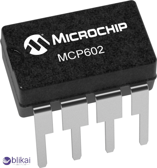
The MCP602 is commonly available in an 8-pin configuration, with pins dedicated to non-inverting input, inverting input, output, positive supply, and ground. In dual-op-amp variants, the pinout allows two independent amplifiers to be housed within a single package, sharing common power pins.
Absolute Maximum Ratings and Operating Conditions
Voltage, Current, and Temperature Limits
The absolute maximum ratings specify the threshold beyond which irreversible damage to the MCP602 can take place. These will be the maximum supply voltage, input voltage relative to the rails and operating temperature range. Exceeding these limits, even briefly, can degrade the internal transistor structures and compromise long-term reliability.
Recommended Operating Conditions
The designers would be required to adhere to recommended operating conditions as stipulated in the datasheet in order to ensure the steady and stable operation. The working conditions of the amplifier must be within the specified voltage and temperature dependencies to be certain that the amplifier satisfies its quoted accuracy, noise, and stability specification, of particular concern in fine adjustment measurement and regulation systems.
MCP602 Internal Architecture and Working Principle
Internal Block Diagram Overview
The MCP602 is internally configured with the use of a differential input stage, a high-gain amplification stage and a rail-to-rail output buffer. The differential input stage compares the voltages of the inverting and non-inverting inputs and the difference is multiplied at the gain stage. The output stage then delivers the amplified signal with sufficient drive capability to interface with loads such as ADC inputs or other analog circuitry.
How MCP602 Achieves Low Power Consumption
The internal architecture of low power consumption is accomplished by the optimization of biasing and transistor choice. The MCP602 has been developed in such a way that it minimizes the amount of statical current whilst still being able to perform well in dynamic effect enabling it to be continuously active in battery operated systems without taking up too much energy.
Typical MCP602 Application Circuits
Voltage Follower and Buffer Circuits
In a voltage follower configuration, the MCP602 provides unity gain buffering, isolating a high-impedance signal source from a low-impedance load. This application is common in sensor interfaces and ADC front ends, where preserving signal integrity is critical.
Non-Inverting and Inverting Amplifier Designs
MCP602 may be configured to use simple resistor networks as a non-inverting or inverting amplifier. The designers are able to achieve set gain levels by choosing the right resistor values, as well as enjoying the rail-to-rail effects and the low offset behavior of the amplifier.
Sensor Signal Conditioning Applications
A lot of sensors generate low level analog data which must be amplified and filtered prior to conversion to digital data. The MCP602 is equally appropriate when conditions of temperature sensors, pressure sensors and photodiodes need to be conditioned in that it can provide the necessary amplification precisely without creating any significant noise or distortion.
Active Filters and Audio Signal Processing
The MCP602 is a low frequency audio and active filter circuit audio amplifier, and is not a high speed audio amplifier. Its predictable gain and low noise floor make it suitable for applications such as tone control, signal smoothing, and low-pass or high-pass filtering.
MCP602 in Low-Voltage and Battery-Powered Systems
Performance in Single-Supply Designs
Single-supply operation makes power management easier and eliminates a greater number of components. The MCP602 excels in single-supply designs by maintaining linear behavior even when the input signal approaches ground, eliminating the need for negative supply rails.
MCP602 for Portable and IoT Devices
In portable electronics and IoT nodes, energy efficiency is paramount. The MCP602 has a low quiescent current which means that it can be continually monitored in analog mode without draining the battery considerably, and hence is a good candidate to the always-on sensing and control capabilities.
MCP602 vs MCP6002 vs MCP6001
Key Specification Comparison
Although the MCP602, MCP6002, and MCP6001 are similar in terms of design philosophy, they are differentiated by the speed, bandwidth and noise characteristics. The MCP602 typically offers improved performance over ultra-low-power variants while still maintaining efficient operation, positioning it as a balanced choice for general-purpose analog tasks.
Design Considerations and Best Practices
Input Common-Mode Range and Output Swing
The MCP602 contains provisions of rail-to-rail operation, but still, the designers need to consider realistic limits in the loading conditions. It is also important to ensure that the input and output signals do not go outside the specified range to avoid distortion and saturation.
PCB Layout and Decoupling Guidelines
The proper PCB layout is the key to the reduction of noise and the stability of operation. Placing decoupling capacitors close to the power pins and maintaining short signal paths reduces susceptibility to interference and oscillation.
Stability, Gain, and Compensation Tips
While the MCP602 is internally compensated for unity gain stability, high-gain configurations or capacitive loads may require careful design to avoid instability. Adherence to data sheet recommendations would ensure a consistent performance.
Common MCP602 Problems and Troubleshooting
Output Saturation and Clipping Issues
Output saturation typically occurs when the amplifier is driven beyond its output swing limits or when the load current exceeds its capability. These problems can be overcome by altering gain or decreasing load demand.
Noise, Offset, and Drift Concerns
Offset drift and noise can be generated by environmental changes such as change in temperature. In precision applications, it is possible to select the right filtering and calibration methods to reduce these effects.
FAQs
Is MCP602 rail-to-rail input and output?
The MCP602 does support rail-to-rail input and output, so it is possible to use signals near both supply rails.
What supply voltage does MCP602 require?
The MCP602 is normally supplied by one source of between 2.5V and 5.5V.
Can MCP602 replace LM358?
In many low-voltage applications, the MCP602 can replace the LM358, offering better rail-to-rail performance and lower power consumption.
Conclusion
The MCP602 op amp is a low-power, rail-to-rail, general purpose, 200 V operational amplifier that is specifically designed to fit low voltage electronics of modern times. By combining efficient power consumption with reliable analog performance, it enables designers to build compact, accurate, and energy-efficient circuits across a wide range of applications. The MCP602 is still a trusted and viable solution to engineers who want a general-purpose op amp that is balanced and fits well into embedded systems and portable ones.
Some images are sourced online. Please contact us for removal if any copyright concerns arise.


