


What is the LM393 IC?All You Need to Know
The integrated circuit LM393 contains two internally integrated operational amplifiers that are internally compensated for frequency. These ICs are specifically engineered to perform various tasks using a single power supply and can also operate effectively with a split power supply. The current drain of the device is independent of the power supply voltage. One of its notable features is the inclusion of ground in its common-mode input voltage. The applications of this IC span across various real-life fields, including industrial applications, analog-to-digital converters (ADCs), battery-powered electrical systems, time-delay generators, and limit comparators. This article provides an overview of the LM393 IC and its functionality.
What is the LM393 IC?
The LM393 is a dual independent precision voltage comparator integrated circuit that operates with either a single or split supply. These ICs consist of two independent voltage comparators designed to function from a single power supply across a wide range of voltages. Operation with dual supplies is also possible as long as the difference between the two supply voltages ranges from 2 volts to 36 volts, and VCC is at least 1.5 volts higher than the input voltage. The primary features of this IC include the following:
- Single voltage supply ranges from 2.0 Vdc to 36 Vdc
- Split supply range spans from +1.0 Vdc or -1.0 Vdc to +18 Vdc or -18 Vdc
- Low supply voltage current drain of only 0.4 mA
- Low input bias current of 25nA
- Low input offset current of 5nA
- Equivalence of both the differential input range and the Power Supply Voltage
- Output voltage is compatible with ECL, MOS, DTL, TTL, and CMOS logic levels
- Electrostatic discharge protection on the inputs enhances device ruggedness without affecting its performance.
LM393 IC Pin Configuration
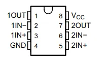
The LM393 IC is equipped with 8 pins, each serving distinct functions. The functions of each pin are outlined below:
- Pin 1 (OUTA): Output A
- Pin 2 (In A-): Inverting input A
- Pin 3 (In A+): Non-inverting input A
- Pin 4 (GND): Ground
- Pin 5 (INB+): Non-inverting input B
- Pin 6 (INB-): Inverting input B
- Pin 7 (OUTB): Output B
- Pin 8 (Vcc): Voltage Supply
LM393 IC Package & Dimensions
The LM393 is available in various package forms tailored to different requirements.
The LM393 IC is housed in an SOIC (8) package, identified by the part number LM393N.
These ICs are offered in diverse packages with varying dimensions to facilitate easy differentiation.
The package type and dimensions of the LM393 IC are SOIC (8) with dimensions of 4.9 X 3.91 mm.
LM393 IC Ratings
The ratings of the LM393 IC primarily encompass current, voltage, and power specifications.
- Input voltage range: -0.3V to 36V
- Differential input voltage: 36V
- Maximum lead temperature: 260°C
- Power Dissipation: 660mW
- Storage temperature range: -65°C to 150°C
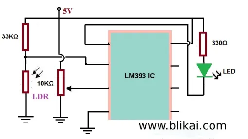
LM393 IC-based Night Light Circuit
This circuit employs a photoresistor to regulate the voltage divider circuit. When the circuit detects bright light, the output device is turned off. Conversely, when darkness is detected, the output device is activated. The operation of this circuit is based on the voltage comparator principle. If the voltage at the inverting terminal of the IC is higher than that at the non-inverting terminal, the output device is activated. Conversely, if the voltage at the inverting terminal is lower than that at the non-inverting terminal, the output device is deactivated. In this circuit, an LED is utilized as the output device.
The necessary components for this circuit primarily include the LM393 IC, a photoresistor or light sensor, resistors (33KΩ & 330Ω), potentiometer, LED, and a battery for power supply. The LM393 IC features two power inputs, namely Vcc and GND. Vcc serves as the positive voltage supply, which can range up to 36V, while GND is the ground connection. These two terminals complete the power circuit and provide the necessary supply for the operation of the circuit.
The LM393 IC incorporates two internally integrated operational amplifiers, each featuring two inputs and one output. These op-amps function autonomously, generating their respective outputs. However, in this circuit, only one operational amplifier is utilized, while the other remains unconnected. Both op-amps are essential only in scenarios involving complex circuits with multiple monitoring levels. As this circuit only checks a single level, it employs just one op-amp.
Upon application of power to the IC, voltage values are compared. If the voltage at the inverting terminal exceeds that at the non-inverting terminal, the op-amp output will be driven to ground, resulting in current flow from the positive supply to GND. Conversely, if the voltage at the inverting terminal is lower than that at the non-inverting terminal, the op-amp output will remain at the positive voltage supply (Vcc), and no current will flow due to the absence of potential difference across the load.
Thus, when the voltage at the inverting terminal is high, the load is activated, whereas when the voltage at the inverting terminal is low, the load is deactivated. In this circuit, an LED serves as the load. The night light circuit utilizing the LM393 is depicted below. This setup employs an LED as the load, with a photoresistor employed for light detection. The resistance of the photoresistor varies based on the intensity of light it detects. In darkness, the resistance of the photoresistor increases, whereas in bright light, its resistance decreases.
To create a voltage divider circuit, a photoresistor and a fixed resistor are connected. In darkness, the photoresistor utilizes more voltage due to its lower resistance, whereas in bright light, it utilizes less voltage.
By configuring the non-inverting terminal of the op-amp with a suitable reference voltage and adjusting the photoresistor's voltage relative to this reference, we have constructed a comparator circuit. This circuit functions differently in darkness compared to bright light. Consequently, the LED illuminates during darkness and turns off in bright light.
So, this concludes the discussion on the LM393 IC and its applications. The LM393 IC serves as a low-power, single-supply, low-offset voltage, dual, differential comparator. Typically, a common comparator IC functions akin to a miniature voltmeter equipped with switches. It is utilized to measure the voltages at two different terminals and compares the difference in voltage levels. If the voltage at the first terminal exceeds that at the second terminal, the switch is activated. Conversely, if the voltage at the first terminal is lower than that at the second terminal, the switch is deactivated. Now, here's a question for you: What are the applications of the LM393 IC?
FAQ
What is the role of the LM393 IC?
The LM393 series comprises dual independent precision voltage comparators capable of operating with single or split supplies. These devices are engineered to accommodate a common mode range that extends to ground level during single supply operation.
What is an alternative to LM393?
The LM393 Comparator IC Pinout, Datasheet, Equivalents & Features
The LM393 is functionally akin to the LM311 Comparator IC, with slight variations in specifications. In essence, the LM311 can serve as a close substitute for the LM393.
What is the function of LM393P?
While the LM393 is technically an amplifier, it is primarily intended for use as a comparator. Consequently, it is designed with a high gain and an open collector output. By loading the open collector output with a resistor and applying feedback, the gain can be reduced, effectively transforming it into a linear amplifier.
Is LM393 analog or digital?
The LM393 LDR Module is a precision light sensor capable of detecting light presence and intensity. It offers both digital and analog outputs, rendering it adaptable for various applications. Utilizing a high-quality LM393 voltage comparator, the module digitizes the analog signal from the LDR sensor.


