


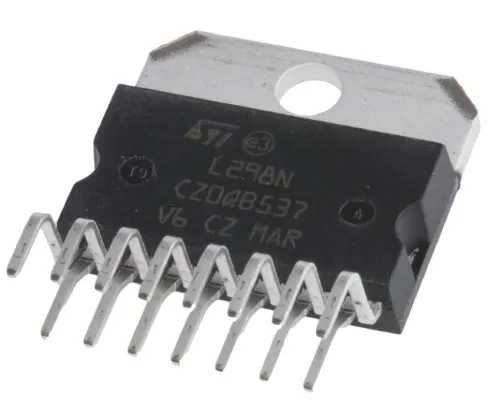
What L298 Motor Driver IC is :Pinout and & Applications
An L298 Motor Driver IC is a monolithic chip used in motor driver modules to control the speed of a DC motor. Currently, other frequently used motor driver ICs include the L293D and L2938N. The L298 IC is commonly found in RC cars and autonomous robots. The input provided to a motor driver module comes from a controller like Arduino.
This logic input is used to control the direction of the motor connected to the motor driver IC. The motor driver module mainly consists of a motor driver IC, which is a crucial component in the module. While this single IC can control the motor alone, interfacing it with Arduino via a motor driver module simplifies the process. This article provides an overview of the L298 motor driver IC, its working principles, and applications.
What is L298 Motor Driver IC?
The L298 Motor Driver IC is a high-power version of the L293 motor driver IC. It is a dual full-bridge driver IC with high current and voltage capabilities, primarily designed to allow typical TTL logic levels to control various inductive loads such as DC motors, solenoids, relays, and stepper motors. The motor driver functions as a small current amplifier, using a low current signal to provide a high current signal necessary for driving an electric motor.
The L298 IC includes four separate power amplifiers, with two amplifiers forming H-bridge A and the other two forming H-bridge B. One H-bridge is used to switch polarity for controlling motor direction, while a pair of H-bridges is used to control a bipolar stepper motor.
Each bridge in this IC has two current sense pins (CSA and CSB) and enable pins (ENA and ENB). The current sense pins are typically connected to the ground terminal but can also include a low-value resistor to measure voltage relative to the current. The enable pins can be used to activate all outputs simultaneously. All the enable and input pins in this IC operate with 5V TTL logic, simplifying the connection with various microcontrollers.
L298 Motor Driver IC Pin Configuration:
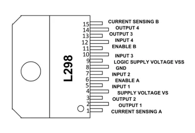
The L298 dual full-bridge driver IC has 15 pins, each serving a specific function within the dual H-bridges (H-bridge A and H-bridge B). The pin functions are as follows:
- Pin 1 (Current Sensing A): This pin is used to monitor and control the current flow of the load connected to H-bridge A.
- Pins 2 & 3 (Output 1 & 2): These are the output pins for H-bridge A, where the current is supplied to the load and monitored via Pin 1.
- Pin 4 (VS): This is the voltage supply pin, connected to +5V.
- Pins 5 & 7 (Inputs): These are the control inputs for H-bridge A and are TTL compatible.
- Pin 6 (Enable A): This is the enable input for H-bridge A, and it is TTL compatible.
- Pin 8 (GND): This is the ground pin.
- Pin 9 (Logic Voltage Supply): This pin provides the voltage supply for the logic blocks.
- Pins 10 & 12 (Inputs 3 & 4): These are the control inputs for H-bridge B and are TTL compatible.
- Pin 11 (Enable B): This is the enable input for H-bridge B, and it is TTL compatible.
- Pins 13 & 14 (Output 3 & 4): These are the output pins for H-bridge B, where the current flow to the load is monitored via Pin 15.
Features & Specifications:
The features and specifications of the L298 IC include the following:
- Operating voltage supply: Up to 46V
- Total DC current: Up to 4A
- Low saturation voltage
- Over-temperature protection
- Power dissipation: 25W
- Operating voltage range: +5V to +46V
- Maximum supply voltage: 50V
- Maximum input & enable voltage: +7V
- TTL controlled inputs
- Storage temperature range: -40°C to 150°C
- Operating temperature range: -23°C to 130°C
- Maximum allowed current flow through each output: 3A
- How to use L298 Motor Driver IC/Circuit Diagram
To understand the working of the L298 motor driver IC, consider the following simple circuit configuration. In this circuit, one H-bridge of the L298 IC is used. The circuit includes two push buttons, denoted Q1 and Q2, to control the inputs of bridge A.
These logic inputs are provided through a microprocessor or microcontroller within application circuits. The four diodes in the circuit are flyback diodes that protect the IC from voltage spikes.
The function of bridge A mainly depends on the enable pin. When the enable pin is pulled high using a resistor, bridge A is enabled and starts working. Conversely, when it is pulled to GND, it is disabled and stops working.
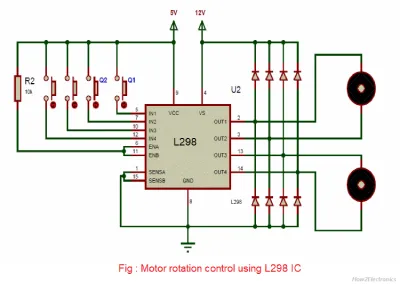
Once the circuit is connected, pressing the two buttons, Q1 and Q2, will change the current flow between the two output pins, OUT1 and OUT2.
The logic control follows as:
- When push button Q1 is high and Q2 is low, the current flows forward.
- When push button Q1 is low and Q2 is high, the current flows in reverse.
- When both push buttons are equal (Q1 = Q2), the motor stops quickly.
If the Q1 push button is pressed, the current flows from Output1 to Output2, causing the motor to rotate clockwise. Conversely, if the Q2 push button is pressed, the current flows from Output2 to Output1, causing the motor to rotate counterclockwise.
If both push buttons, Q1 and Q2, are pressed or released simultaneously, the motor will stop immediately. Thus, the motor speed can be controlled using an L298 motor driver IC.
Where to use L298 Motor Driver IC/Applications:
The applications of the L298 motor driver IC include the following:
- Robotics and Embedded Systems: The L298N motor driver IC is widely used in robotics and embedded systems. Microcontrollers operate at low voltage and current, whereas motors require higher voltage and current. Motor driver ICs like the L298 are used to bridge this gap by providing the necessary high voltage and current to the motors.
- H-Bridge Applications: The L298 motor driver is suitable for applications involving H-bridges.
- High Power Applications: This motor driver is used in applications requiring high power.
- Current Control and PWM: The IC is employed where current control and PWM operable ICs are needed.
- TTL Output Control: It is used in scenarios where the control unit provides only TTL outputs.
The L298 Motor Driver IC is versatile in controlling motor direction. Various motor driver ICs are available in the market based on maximum voltage supply, load voltage, maximum output current, rated power dissipation, and the number of outputs. Generally, the L298 motor driver IC is used to control the speed of DC motors, simplifying DC motor interfacing with a microcontroller.
Here is a question for you: Please mention different motor driver ICs.


