


How to Use LM3914: Circuit Diagram, Features, and Tips
Introduction
The LM3914 is a general-purpose analog display driver integrated circuit capable of transforming an analog input signal into a visual representation using an LED. LCD bar graphs or dots Switches are simple to construct, precise LED bar graphs or dots patterns, whether you are designing a straightforward battery display or a high-tech audio visualizer. This guide will discuss how the LM3914 functions, its functionality, major circuits and good design tips to incorporate in your electronics designs.
What is the LM3914?
LM3914 is an LED driver IC that is meant to drive 10 LEDs within a linear range of voltage. It eases the task of representing the analog voltages with the visual output, such as LED, LCD, or vacuum fluorescent display. Its internal work consists of a voltage reference, a chain of comparators and output drivers that switch LEDs incrementally with an increase in input voltage.
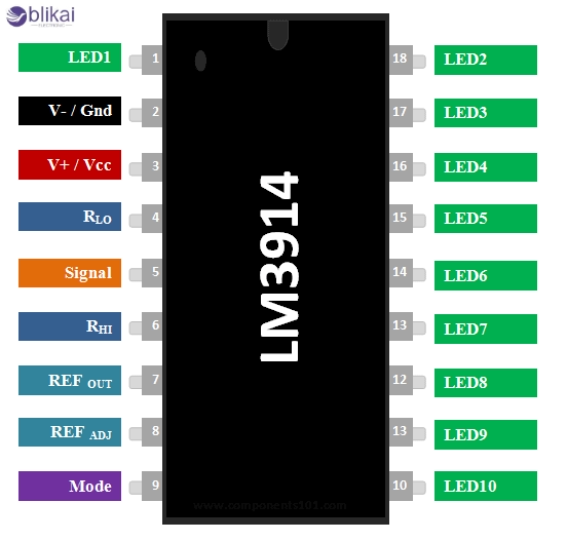
Pin Configuration:
| Pin | Function |
| - | |
| 1–10 | LED Outputs 1–10 |
| 11 | Ground |
| 12 | V- (Signal GND) |
| 13 | LED Current Prog |
| 14 | Reference Out |
| 15 | Reference Adj |
| 16 | V+ (Power Supply) |
| 9 | Mode Select (Dot/Bar) |
- Common Package: DIP-18 or SOIC-18
- Operating Voltage: 3V to 25V
- Output Type: Current regulated for each LED
Key Features of the LM3914
- Drives 10 LEDs directly without external resistors
- Adjustable reference voltage from 1.2V to 12V
- Selectable display mode: dot or bar graph via pin 9
- Linear LED response (each LED represents equal voltage steps)
- Low power consumption
- Cascadable with multiple ICs for more LEDs (20, 30, etc.)
LM3914 Circuit Diagram
1. Basic LED Bar Graph Display Circuit
Here’s a simple LM3914 circuit that lights up 10 LEDs in response to input voltage (0V to 5V):
- Vin --> Pin 5 (Signal In)
- Vcc = 5V --> Pin 16
- Ground --> Pin 11, 12
- LEDs connected from Pin 1-10 through cathode to GND
- R1 & R2 between Pin 7, 8, and Ground to set reference voltage
- Pin 9 connected to Vcc for bar mode
Each LED lights up for every 0.5V step (assuming 0–5V range)
You can adjust the voltage range by selecting different R1 and R2 values
Leave pin 9 open or connect to ground for dot mode
2. Battery Level Indicator Circuit
You can easily monitor a battery (e.g., 12V lead-acid) using LM3914:
- Input: Voltage divider reduces 12V to 1.2V–5V for the LM3914 input
- Display: LEDs show levels such as 10%, 20%, … up to 100%
- Protection: Use a zener diode or voltage regulator to protect the IC from overvoltage
- Application: Ideal for solar battery banks, UPS systems, or electric vehicles
3. Cascading Multiple LM3914 ICs
To display more than 10 levels:
- Connect pin 9 of the first IC to ground (dot mode), and the second IC to Vcc (bar mode)
- Tie the reference outputs together for a common scale
- Use a resistor ladder between reference outputs for voltage steps
Example: Cascading three LM3914s gives a 30-LED visual scale, suitable for audio or signal level meters.
How to Use the LM3914: Step-by-Step Guide
Step 1: Define the Voltage Range
Decide the minimum and maximum voltages you want to display. Example: 0V to 10V.
Step 2: Set Display Mode
Connect Pin 9 to Vcc for bar mode
Leave open or connect to GND for dot mode
Step 3: Configure Reference Voltage
Use resistors R1 and R2 on pins 7 and 8
Vref = 1.25V × (1 + R2/R1) + Iadj × R2
Step 4: Connect LEDs
Anodes to output pins (1–10), cathodes to GND
No series resistors needed
Step 5: Apply Power and Test
Power supply to pin 16 (Vcc), ground to pin 11
Input signal to pin 5
Observe LED display behavior
Tips for Designing with LM3914
- Use precise resistors for voltage references to ensure accuracy
- Place a 0.1μF decoupling capacitor between Vcc and ground near the IC
- Use high-efficiency LEDs to reduce power consumption
- Minimize wiring lengths to prevent voltage drops
- Use dot mode for lower power when using battery-powered devices
- Avoid overheating when driving high-current LEDs continuously
Common Applications of LM3914
LED Bar Graph Voltmeters
Simple LED bar graph voltmeters may be constructed using the LM3914. It can accept an analog voltage signal and can drive 10 LEDs linearly, and hence it is the perfect device to be used to represent the voltage in the form of a visual representation. The LEDs are related to distinct voltages, and users can read the voltage status in a short period. Examples of such applications include power supplies, battery testers and control panels.
Battery Level Indicators
The other common application of the LM3914 is battery charge level indicators. With the IC connected to a battery with the aid of a voltage divider, a row of LEDs could be illuminated to show the degree of battery charge or discharge. This can find special application in portable electronic equipment, battery chargers and dashboards of electric cars, where users need a swift, clear means to understand how much battery is left.
Audio Level (VU) Meters
Common usage in audio systems is to make VU (Volume Unit) meters with the LM3914. These gadgets illuminate LEDs corresponding to audio amplitude, locking lights to show the strength of the audio signal visually. Audio peak and general sound dynamics can be monitored by using LM3914-based VU meters in mixers, amplifiers and audio signal processors by musicians, audio engineers and hobbyists.
Temperature Level Display
The LM3914 may also be used as a temperature level indicator with the addition of temperature sensors like the LM35. This analog voltage signal is connected to the LM3914, which drives the LEDs in a bar graph that indicates the value of the temperature. Such an arrangement is present in HVAC-relevant equipment, manufacturing systems monitoring devices, and e-thermometers, and enables an unambiguous real-time graphical display of the temperature conditions.
Pressure or Sensor Output Monitoring
The value of the sensor measuring pressure, humidity, or gas concentration is commonly in analog voltages, which makes the LM3914 an outstanding option in displaying the result. Since the analog signal provided by the sensor can be translated to a similar-looking LED bar graph by LM3914, this means an end user can visually review any environmental/system changes in real time. It is commonly applied to industrial automation, laboratory instruments and smart home equipment.
Solar Panel or Inverter Output Display
LM3914 can be applied in monitoring and pixel displaying the value of the voltage supplied by solar panels or inverters in renewable energy. This will enable clients to monitor power generation or the load on a real-time basis. The bar graph value has better display over the normal digital displays, and noticing any pattern or defect in the system is easy.
Adjustable Power Supply Monitoring
The LM3914 is common in DIY or professional electronics work to indicate visually the output voltage of variable power supplies. LM3914 lights up appropriate LEDs as the output voltage is changed up or down, and the current setting can quickly be checked. This negates the necessity of continual use of a multimeter and makes bench power supplies more useful.
Current Level Display with Shunt Resistor
LM3914 may also be used to indirectly display current levels by measuring the voltage across a shunt resistor. The voltage difference (that is known as current) is measured, and the same value goes to the IC that lights up LEDs. This is useful in neuropil circuits, battery control, and power monitoring systems, where it is useful in diagnostic and optimization to visualize current flow.
Light Intensity or LDR-Based Display
LM3914 can be used to convert ambient light levels into LED bar graphs, using an LDR ( Light Dependent Resistor ) in a voltage divider. The application can be used in ambient light monitoring systems, automatic lighting systems, and learning applications. It can be used to monitor in real-time the varying light conditions, and it can be used to provide feedback control or environmental sensing.
Educational and Demonstration Kits
Owing to its ease of use and appearance in a graphic display, the LM3914 is a popular component of educational electronic kits and demonstration projects. It assists students and amateurs in learning the fundamentals of analog to digital conversion, measurement of voltage and driver of LED. This simple nature and flexibility to be used to work with many different analog inputs make it useful to have in the hands-on learning environment.
LM3914 vs LM3915 vs LM3916
|
Feature |
LM3914 |
LM3915 |
LM3916 |
|
Output Scale |
Linear (Equal Steps) |
Logarithmic (3dB/step) |
VU meter scale (audio tuned) |
|
Application |
General voltage display |
Audio level meters |
VU meters in audio circuits |
|
Best For |
Battery/sensor level |
dB scales, music visualization |
Hi-fi stereo level displays |
- LM3914 is best for general-purpose voltage displays
- LM3915 and LM3916 are more suited to audio applications
Frequently Asked Questions (FAQ)
Q1: How many LEDs can LM3914 drive?
10 LEDs can be driven with a single LM3914. There are ways of cascading multiple ICs to support 20, 30 or more LEDs.
Q2: Can LM3914 work with Arduino?
Yes. By using PWM, you can print to a variable analog voltage and filter this to drive LM3914.
Q3: Do I need current-limiting resistors for LEDs?
No. The LM3914 regulates current internally using pin 7 (Rset).
Q4: How do I switch between dot and bar mode?
Tie pin 9 to Vcc in bar mode or float/GND in dot mode.
Conclusion
LM3914 is a versatile and simple-to-use integrated circuit that allows the representation of analog voltages with LEDs. The LM3914 can both save you time and parts when making your own battery monitor or sensor display, and also provide you with a professional-looking visual output. With an insight into its layout, capabilities, as well as its usage in actual circuits, you can release a plethora of applications in your electronic designs.


