


Solid State Relays (SSR): How They Work & Applications
What Is a Solid State Relay (SSR)?
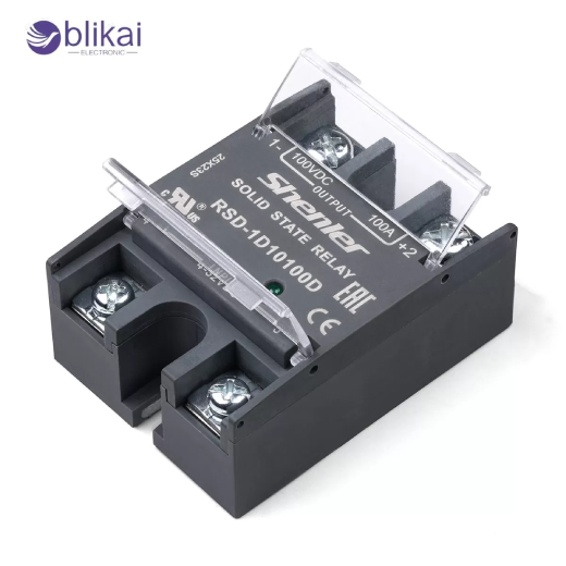
Solid state relay: An electronic relay that makes use of semiconductor devices such as optocouplers, triacs, SCRs or MOSFETs to switch electrical loads. It does the same simple job as a mechanical relay isolating a control signal of a high-power load, except that there are no physical contacts. The SSRs are free of moving parts, and therefore any disturbances such as contact wear, arcing and mechanical noise are removed, making them best suited to tools that need high reliability and frequent switching.
Basic Function of a Solid State Relay
The primary function of an SSR is to allow a low-power control signal to safely switch a high-voltage or high-current load. With the input signal, the internal electronic circuitry will power the output switching device so that a current is passed through the load. When the control signal is disconnected, the output device is shut off, and the flow of current is cut off, and this is without any mechanical action or clicking.
Main Components of a Solid State Relay
Solid state relays are made up of various internal components that combine to make the supply safe and efficient switching, but retain electrical isolation between the control and load sides.
Input Circuit
The input circuit of an SSR is designed to accept a control signal, typically DC or AC, from a controller such as a PLC, microcontroller, or temperature controller. This input is typically low-power, and SSRs can be used with logic-level signals and control electronics of modern control.
Optical Isolation (Optocoupler)
One of the most significant characteristics of a Solid state relay is optical isolation. An optocoupler employs light to pass the control signal within the optocoupler, so no electrical connection is provided between the input and output circuits. This isolation improves safety, protects sensitive control electronics, and reduces the risk of electrical noise and voltage spikes reaching the control side.
Output Switching Device
The output stage of an SSR contains the semiconductor device responsible for switching the load. Depending on the relay type, this may be a triac or SCR for AC loads, or a MOSFET or IGBT for DC loads. The output device selected defines the voltage rating, the current capacity, as well as the appropriateness of the relay to various applications.
How Solid State Relays Work
A solid state relay works by the principle of electronic control of the signal without the need for mechanical movement, and hence, a solid state relay can switch with precision and speed.
Control Signal to Load Switching Process
In the event of a control voltage being applied to the input terminals, current passes through the input circuit and causes the optocoupler to be activated. The optocoupler releases light, which activates the output semiconductor device, turning it on and enabling current to pass through the load. When removed, the optocoupler will cease its light emission and close the output device, leaving the load current interrupted.
Zero-Cross vs Random Turn-On Operation
Zero-cross switching A subcategory of SSRs, is intended to turn-on only upon the AC waveform passing through zero voltage. This decreases electrical noise and inrush current. Random turn-on SSRs, however, turn-on when the control signal is added and turn-off when the control signal is removed, and they are therefore applicable to a phase-angle control as well as in processes that demand precise timing.
Types of Solid State Relays
Solid state relays can be classified based on the type of load they control and their internal switching technology.
AC Solid State Relays
AC SSRs are designed to switch alternating current loads and typically use triacs or SCRs as output devices. They are widely used in heating systems, lighting control, and industrial automation, where AC power is standard.
DC Solid State Relays
DC SSRs use MOSFETs or IGBTs to switch direct current loads. The applications of these relays include battery-operated systems, the control of DC motors and in renewable energy. DC SSRs are also subject to voltage and polarity, though, unlike AC SSRs, DC SSRs demand attention to polarity.
Single-Phase vs Three-Phase SSRs
Single-phase SSRs operate a single AC/DC circuit, with three-phase SSRs intended to operate three-phase power systems. Three-phase SSRs are often used in industrial motor control, heating equipment, and high-power automation systems.
SSR Type Comparison Table
The table below gives a direct comparison of typical Solid state relay types in terms of type of load and switching behavior.
|
SSR Type |
Load Type |
Output Device |
Typical Applications |
Key Advantages |
Main Limitations |
|
AC SSR |
AC |
Triac / SCR |
Heaters, lamps, HVAC |
Simple design, long life |
Not suitable for DC |
|
DC SSR |
DC |
MOSFET / IGBT |
DC motors, batteries |
Fast switching, low noise |
Higher cost |
|
Zero-Cross SSR |
AC |
Triac / SCR |
Resistive loads, heaters |
Low EMI, reduced inrush |
Not for phase control |
|
Random Turn-On SSR |
AC |
Triac / SCR |
Dimmers, motor control |
Precise timing |
Higher EMI |
Solid State Relays vs Electromechanical Relays
It is a matter of performance needs, environment and needs of the application that would lead to a choice of SSR selection versus mechanical relay selection.
Switching Speed and Lifetime
Solid state relays also operate at much higher speeds compared to electromechanical relays and have the capability to operate millions of times. Contact erosion and mechanical fatigue are the limits to the life of mechanical relays.
Noise, Arcing, and Vibration Resistance
SSRIs are also silent and do not generate any contact arcing, which makes them the perfect choice in sensitive noise settings. They also resist vibration and shock very well, unlike the mechanical relays.
Power Loss and Heat Dissipation
One drawback of SSRs is the on-state voltage drop, which leads to power loss and heat generation. Mechanical relays typically have lower on-state losses but suffer from arcing during switching.
Advantages of Solid State Relays
Solid state relays possess a number of benefits that ensure that they are now a favorite in contemporary electronic systems.
Long Service Life and Reliability
Since SSRs do not contain moving components, they enjoy low mechanical wear, making them have long working lifestyles and they are also very reliable even in harsh environments.
Fast Switching and High Frequency Operation
SSRIs are able to quickly switch and cope with very high-frequency operation, which is why they are used in pulse-width modulation or very close control applications.
Disadvantages of SSRs
Despite their benefits, SSRs also have limitations that must be considered during system design.
Heat Generation and Thermal Management
The SSRs have the ability to dissipate internal power, so heat sinks or proper ventilation are required to prevent potential overheating and ensure the stable operation of the SSRs.
Leakage Current and Off-State Voltage
SSRs may allow a small leakage current even when turned off, which can cause sensitive loads to remain partially energized.
Common Applications of Solid State Relays
Solid state relays find application in a large variety of industries and systems.
Industrial Automation and PLC Control
SSRs are also applied in automation systems to connect the outputs of PLCs to high-power loads such that the switching between them is fast and reliable with little maintenance.
Heating and Temperature Control Systems
SSRs are commonly used in temperature controllers to regulate heaters, ovens, and furnaces due to their ability to handle frequent switching without wear.
Motor Control and Power Switching
Although SSRs are not always the best for high-inrush motor loads, they can be used in soft-start and controlled switching.
Medical, Laboratory, and Precision Equipment
The quietness of operation and high reliability of SSRs allow their use in medical equipment and laboratory equipment where noise and vibration are to be reduced.
How to Choose the Right Solid State Relay
The choice of the right SSR is the key to safe and effective working.
Load Voltage and Current Ratings
Always choose an SSR with voltage and current ratings higher than the actual load, accounting for inrush current and derating factors.
Control Voltage Compatibility
Make sure the SSR input voltage is the same as the control signal of the PLC or controller; otherwise, the switching would be unreliable.
Environmental and Installation Factors
Take into account ambient temperature, mounting design, and enclosure design so as to have sufficient heat dissipation and reliability in the long-term.
Installation and Safety Considerations
Proper installation greatly affects SSR performance and lifespan.
Proper Heat Sink Selection
An appropriate heat sink helps in minimizing thermal stress and premature failure, particularly in high current.
Protection Against Overvoltage and Overcurrent
Adding fuses, MOVs, or snubber circuits helps protect SSRs from voltage spikes and short circuits.
FAQ
Can SSRs switch both AC and DC loads?
The majority of SSRs are engineered to be used either with AC or DC loads, but not both, so one should make the right choice.
Why do Solid state relays get hot?
Internal voltage drop creates heat, and power dissipation occurs when the item is operating.
When should I choose an SSR over a mechanical relay?
SSRs are used in situations where there is a need to operate quietly, quick switching and extended service life.
Conclusion
The importance of Solid state relays in the current electronics and industrial control systems lies in offering reliable and fast switching without any noise. The knowledge of the principles of SSRs, their type, benefits, and limitations can assist engineers and technicians to choose the correct relay in a specific application. Solid state relays provide an effective and long-lasting solution to the control of electrical loads in a wide variety of conditions with appropriate selection, installation, and thermal control.
Some images are sourced online. Please contact us for removal if any copyright concerns arise.


