


Pull-Down Resistor Explained: With Real Circuit Examples
Introduction
In the present-day electronic circuit design, it is paramount that all the signal lines possess a well-defined voltage condition to be stable and reliable. The pull-down resistor is one of the least complicated and yet the most important elements that are employed to attain this objective. Pull-down resistors, though very small and cheap, are important because they help in preventing floating inputs, eliminate the possibility of unpredictable logic behavior, and enhance noise immunity in digital and mixed signal circuits. From microcontroller inputs to transistor switching stages, pull-down resistors are widely used across consumer electronics, industrial control systems, and embedded designs. This paper discusses the theory of a pull-down resistor, its operation, the applications when a pull-down resistor is required and some real circuit examples to guide you on how to use the pull-down resistor correctly in a practical design.
What Is a Pull Down Resistor?
A pull-down resistor is a resistor device that is placed between a signal line and ground (0 V) to guarantee that the signal goes to a logic LOW when no active driving source occurs.In digital electronics, the majority of its inputs are high-impedance i.e. they can absorb practically no current, and they do not approach a steady value. These types of inputs can be left floating and thus will pick electrical noise and provide random or unstable logic readings. By providing a controlled path to ground, a pull-down resistor forces the input voltage to remain near 0 V unless another component actively drives it HIGH.
Why Pull-Down Resistors Are Used in Electronic Circuits
The main purpose of pull-down resistors is to remove floating input conditions, which may cause system behavior that is difficult to predict. Floating inputs are especially problematic in digital logic circuits, where even small amounts of noise can cause false triggering. By defining a default LOW state, pull-down resistors ensure consistent logic interpretation, improve signal stability, and protect downstream components from unintended switching. In safety-critical systems, such as industrial controllers or automotive electronics, pull-down resistors also help guarantee known startup conditions when power is first applied.
Pull-Down Resistor vs Pull Up Resistor
Pull-down resistors draw a signal near to ground whereas the pull-up resistors draw a signal near to the supply voltage (VCC). The decision to use the two is based on the logic polarity, power consumption and circuit architecture. In active-high logic, the pull-down resistors more typically appear in a HIGH signal denoting an asserted or ON state. Pull-up resistors on the contrary are common in active-low designs. Functionally, both components prevent floating inputs, but they influence default logic levels differently and can impact current consumption depending on how often the signal is driven.
How Pull-Down Resistors Work in Digital Logic Circuits
Very high input impedance is usually achieved in digital logic circuits by designing the inputs to logic gates, microcontrollers or flip-flops. This enables them to feel the levels of voltage without loading the circuit, though they are also vulnerable to noise. A pull-down resistor provides a weak but stable connection to ground, overpowering stray electric fields and leakage currents. When another component, such as a switch or output pin, drives the signal HIGH, the resistor limits current flow, preventing a short circuit while allowing the voltage to rise to a valid logic HIGH level.
Typical Pull-Down Resistor Values and How to Choose Them
Depending on the application, values of common pull-down resistor diversity range between 1 kO and 100 kO. Lower resistance values provide stronger noise immunity but increase current consumption when the signal is driven HIGH. The increased values of resistance minimize the consumption of power but can not be as efficient in noisy conditions. In the case of microcontroller inputs, the range of 10 kO to 47 kO is a common range of good compromise between stability and efficiency. Input leakage current, switching speed and environmental noise are also factors that designers should take into consideration during the choice of a pull-down resistor value.
Real Circuit Examples of Pull-Down Resistors
Pull-Down Resistor in a Push-Button Circuit
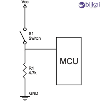
One of the commonest types of circuits containing a pull-down resistor is a push-button input circuit. In the absence of the button, the pull-down resistor maintains the input at logic LOW. When the button is pressed, the input is sent to VCC, the pull-down resistor is bypassed, and logic HIGH is produced. This design has ensured that there is a clean and predictable signal transition which eliminates false button presses caused by noise or bouncing of contacts.
Pull-Down Resistor with a Microcontroller Input
Microcontrollers such as Arduino, STM32, or ESP32 often rely on pull-down resistors to define input states. A pin on input that has not been connected to a pull-down resistor will give a random HIGH or LOW value. An external pull-down resistor may also be added by the designers to make sure that the pin is read as LOW when the signal is not present. The internal pull-down resistors of most microcontrollers are not very accurate, but external resistors can be a better option in challenging applications.
Pull-Down Resistor in Transistor Switching Circuits
The switching circuits that are implemented on transistors are provided with pull-down resistors to inhibit the extraneous activation of the transistor. The pull-down resistor will provide some form of assurance that when the control signal is no longer connected or when the transistor is actually being switched on that the transistor will be in an off state. This is especially important in motor drivers, relays, and power control circuits, where accidental activation could cause damage or safety hazards.
Pull-Down Resistor in Analog and Mixed-Signal Circuits
Even though the term pull-down resistor is most widely considered with digital logic, it is also applied in analog and mixed-signal design. They are able to offer biasing routes, discharge capacitors, and establish reference points in sensor interfaces. In reset circuits, pull-down resistors are used to assist in making certain that control signals are kept at LOW until the system is in stable operational conditions.
Common Mistakes When Using Pull-Down Resistors
The most frequent error is the wrong selection of the value of the resistor, either too small, resulting in unnecessary power loss, or too large, resulting in low noise immunity. The other mistake that is common is to believe that the unused inputs do not require pull-down resistors, which may cause unpredictability. Inadvertently, designers also tend to mix up pull-down and pull-up resistors and use the incorrect configuration.
Pull-Down Resistors and Floating Inputs Explained
A floating input occurs when a signal line is not connected to a defined voltage source or reference. Floating inputs can be considered as antennas to catch the electromagnetic interference effects of the electromagnetic signals around them. Pull-down resistors remove floating inputs by giving the signal a defined electrical path to ground to stabilize it and provide reliable operation under the various environmental conditions.
Internal Pull-Down Resistors in Microcontrollers
Many modern microcontrollers include internal pull-down resistors that can be enabled through software. Floating inputs serve as antennas and intercept the electromagnetic noise of other strong signals. In order to eliminate floating inputs, pull-down resistors are used so as to give a specific electrical path to the ground, stabilizing the signal and allowing the signal to function reliably under varying environmental factors.
Power Consumption and Signal Integrity Considerations
Pull-down resistors introduce a small but continuous current path when the signal is driven HIGH. This current draw is to be taken into consideration in battery-powered machines. Designers must compromise between power efficiency and signal integrity, and resistor values that they would prefer to make as low as possible to reduce the consumption, and maintain the logic levels constant, and noise margins high.
Practical Design Tips for Using Pull-Down Resistors
To achieve optimal performance, pull-down resistors must be mounted near the input pin they are attached to in order to reduce the length of the trace and noise pickup. Lower resistance values and effective PCB grounding methods would help a great deal in high-speed or high-noise environments. The designers should also review component datasheets to get acquainted with the characteristics of the input before deciding on the final values of resistors.
FAQ
What happens if a pull-down resistor is removed?
Without a pull-down resistor, the input may float, leading to unpredictable logic states and false triggering.
What is the difference between a pull-down resistor and a floating input?
A pull-down resistor is used to specify a stable low, where a floating input has no specified voltage but is extremely vulnerable to noise.
Some images are sourced online. Please contact us for removal if any copyright concerns arise.


