


Analog Comparator Explained: Circuit, Operation, and ICs
Introduction to Analog Comparators
An analog comparator is a comparator used in analog or mixed-signal electronics. It mainly compares two voltage levels and produces a digital signal (HIGH or LOW) with, which is higher. Comparators operate in an open-loop mode, unlike the op-amps that have linear mode. Applications These are important devices in constructing logic-level decisions out of analog signals. They are important when analog information in the real world needs to be converted into readable logic signals that microcontrollers or other digital systems can utilize efficiently, such as temperature, voltage, current etc.
Working Principle of an Analog Comparator
The action of a comparator is simple and also effective. The circuit is fed by two analog voltages on its inverting and noninverting pins (inverting ( ) and noninverting (+). Comparatively, the higher voltage is resolved internally by the comparator. When the noninverting input voltage (V +) is greater than the inverting input voltage (V-), then the logic state at the output becomes logic HIGH (close to Vcc). When this is not so (V+ < V), then the output goes to the LOW state (close to ground or 0V). This has a binary output that permits it to be used as a decision component. Also, the comparator can switch rapidly--usually in nanoseconds; therefore, it is suitable for high-speed signal monitoring.
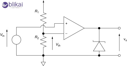
Typical Analog Comparator Circuit Diagram
The most basic comparator circuit normally consists of the actual comparator IC, an input signal, a reference voltage, and a pull-up resistor in the event that the comparator is an open-collector type. An example would be in a battery monitor, whereby the signal source may be a voltage divider connected to the battery and the reference voltage is used to define the threshold. The comparator output switches state when the battery gets below the desired level, representing a low-voltage indication. The modes are inverting and noninverting, which makes it flexible, and designers can select the type of logic they prefer. Hysteresis is sometimes added by feeding back a little of the output into the noninverting input, which can help avoid unstable or noisy switching when the input voltage is almost at the threshold.
Key Features and Specifications to Consider
Some parameters have a significant influence when choosing an analog comparator to put in a design:
Input offset voltage: This small inherent mismatch between inputs determines how precisely the comparator can detect voltage differences. Lower is better.
Propagation delay: The time taken for a change in input to reflect the output. For high-speed designs, look for delays in the nanosecond range.
Input common-mode range: The maximum range of allowed input voltage compared with the supply rails. More flexibility is available with rail-to-rail input comparators.
Output type: There are open-drain or push-pull versions that influence the output interface to logic circuits or LEDs.
Power consumption: It is important in battery-powered devices where low standby current is required.
Popular Analog Comparator ICs
Numerous comparator ICs are available, each tailored for specific applications. Some widely used models include:
LM339: The LM339 is an open-collector quad comparator. It observes four individual lines of voltage, typically with power supplies, fan control and multiple-channel sensor systems.
LM393: Widely used dual comparator that has low input offset Voltage and low power requirements, best suited to battery monitors, light level monitors and alarms.
TLV3501: A high-speed, rail-to-rail input comparator with CMOS output, capable of handling fast-changing signals. It’s used in communication systems, high-speed data acquisition, and waveform shaping.
Applications of Analog Comparators in Real Circuits
Analog comparators serve countless roles in real-world circuits:
Zero-crossing detectors detect when the polarities of AC signals are changing, and they are useful in time and phase measurement.
The use of over/under-voltage detection circuits to power off or warn systems when supplying voltages is more than safety-critical voltages to preserve sensitive electronics.
Comparators are also used in PWM generation, with a ramp / sawtooth waveform being compared to a control voltage to change the duty cycle on a dynamic basis.
Temperature sensing systems incorporate thermistors as well as comparators to activate cooling or overheating fans.
Window comparators, which combine two comparators, detect if a voltage is within or outside a certain range—common in sensor calibration and fault detection systems.
Analog Comparator vs Op-Amp: What’s the Difference?
Whereas comparators and operational amplifiers (op-amps) have similar pin layouts and internal structures, they are intended very differently:
Op-amps are designed for linear operation with negative feedback. They amplify analog signals over a continuous range and are used in audio amplifiers, filters, and integrators.
Comparators, on the other hand, are optimized for digital-like switching behavior. They operate open-loop and react quickly to small differences, outputting either full HIGH or LOW.
Feedback Oscillations will occur when applying an op-amp as a comparator; in low-speed or non-critical applications, this technique might suffice, but otherwise, it is almost inevitably a cause of slow response, possible saturation of the output, or even instability caused by unneeded feedback paths. When you need precision and speed, you should always use a true comparator.
Design Tips and Best Practices
Good comparator design practices ensure accurate, noise-free performance:
Introduce hysteresis; a small fraction of the output may be reintroduced into the input; this introduces a small margin of safety around the threshold value so that toggling can not occur with rapid changes in the input (ripple or noise).
When using comparators, to stabilize the supply voltage and to avoid oscillations, employ bypass capacitors (usually 0.1 m) near the power pins of the comparator.
Maintain short, shielded traces on input signals to avoid interference.
Make sure the source of the reference voltage is clean and regulated - e.g., precision reference IC or regulated voltage divider.
Use a pull-up resistor to correspond with the gate switching speed and the output load in case of open-collector outputs. When the resistance of the load is too great, it takes too long to charge a capacitor; when it is too little, it dissipates more current than necessary.
Troubleshooting Common Comparator Issues
When comparator circuits fail to operate correctly, common culprits include:
Incorrect reference voltage: Double-check the voltage divider or reference IC value.
Missing or incorrect pull-up resistor: Open-collector outputs need a pull-up resistor; without it, the output may always read low.
Noise and instability: Rapid output toggling usually means the input is noisy or hovering near the threshold. Adding hysteresis or filtering capacitors can stabilize the behavior.
Slow switching: This may indicate an overloaded output, poor PCB layout, or a comparator with insufficient speed for the application.
Exceeding input range: Always ensure both inputs remain within the allowable common-mode range, or the output may behave unpredictably.
Conclusion
The analog comparators are quite powerful but extremely basic devices which allow the attainment of voltage level detection along with signal conditioning in a vast variety of applications in electronics. fruits-and-vegetablesWhether it is as battery monitors, digital thresholds, sensor interfaces or PWM systems, you need to know how comparators work and how to apply them properly. Application of suitable IC, careful design of reference voltage and noise reduction are important attributes toward standard results.
Related Articles
Why Using Op Amps as Comparators?
What is an Mechanical Comparator?
What is an LM324 IC Comparator?


