


What is Parity Generator and Parity Checker?Everything You Need yo Know
The primary role of the parity generator and parity check mechanism is to identify errors during data transmission, a concept dating back to 1922. In RAID technology, the parity bit and parity checker serve as safeguards against data loss. The parity bit, an additional bit appended during transmission, can be toggled to '0' or '1', solely tasked with identifying single-bit errors, making it the simplest error detection method. Various error detection codes, including parity, ring counter, block parity code, Hamming code, biquinary, etc., are employed for error detection. Below is a concise overview of the parity bit, parity generator, and checker.
What is the Purpose of Parity Bit?
The parity bit, also known as a check bit, is appended to binary codes to ascertain their parity status, distinguishing between even and odd parity. Parity, determined by the count of 1s, encompasses two variants: even and odd bits.
Odd parity necessitates an odd count of 1s in the code. For instance, in a 5-bit sequence like 100011, with three 1s, it conforms to odd parity. Conversely, even parity mandates an even count of 1s. Consider a 6-bit code such as 101101, with four 1s, adhering to even parity.
What Constitutes a Parity Generator?
Description: The parity generator, an integrated circuit within the transmitter, receives an original message and produces the corresponding parity bit. Subsequently, the transmitter dispatches messages accompanied by their respective parity bits.
Varieties of Parity Generator
Even Parity Generator
Functioning within the even parity generator is the maintenance of binary data with an even count of 1s. For instance, when the data exhibits an odd count of 1s, this generator rectifies it by appending an additional 1 to achieve an even count. Operating as a combinational circuit, its output hinges on the provided input data, exclusively binary in nature.
Let's examine a scenario with three input binary bits denoted as A, B, and C. Utilizing these three bits, we can formulate 23 combinations, ranging from 000 to 111 (0 to 7). The truth table illustrating the behavior of the even parity generator with three input binary bits is presented below:
- 0 0 0: The even parity remains '0' as the input already conforms to even parity.
- 0 0 1: Since there's a single '1' in the input, resulting in odd parity, the even parity generator appends another '1' to achieve even parity.
- 0 1 0: With odd parity exhibited, the even parity is set to '1' to establish even parity.
- 0 1 1: As the input already maintains even parity, the even parity remains '0'.
- 1 0 0: Odd parity necessitates the addition of '1' to attain even parity.
- 1 0 1: The input's even parity dictates that no further adjustments are needed, hence the even parity remains '0'.
- 1 1 0: Similar to the previous scenario, the even parity remains '0' as the input already conforms to even parity.
- 1 1 1: Odd parity prompts the addition of '1' to ensure even parity.
Even Parity Generator Truth Table
| A B C | Even Parity |
| 0 0 0 | 0 |
| 0 0 1 | 1 |
| 0 1 0 | 1 |
| 0 1 1 | 0 |
| 1 0 0 | 1 |
| 1 0 1 | 0 |
| 1 1 0 | 0 |
| 1 1 1 | 1 |
The karnaugh map (k-map) simplification for three-bit input even parity is
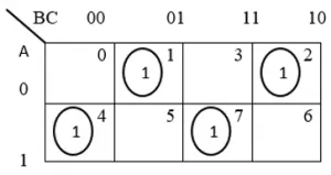
From the above even parity truth table, the parity bit simplified expression is written as
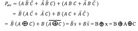
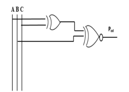
The even parity logic, executed through the utilization of two Exclusive-OR (Ex-OR) gates, is graphically depicted in the logic diagram showcasing the application of Ex-OR gates for achieving even parity.
Thus, the parity generator for even parity ensures the generation of an even count of 1s through processing the input data.
Odd Parity Generator
The odd parity generator ensures the maintenance of binary data with an odd count of 1s. For instance, if the data initially contains an even number of 1s, this odd parity generator adjusts it to have an odd count by appending an additional 1. This circuit operates as a combinational logic, with its output contingent upon the provided input data. It only adds a parity bit if the input has an even count of 1s, transforming the binary code into one with an odd count of 1s.
Consider three input binary bits designated as A, B, and C. The truth table illustrating the behavior of the odd parity generator for three input binary bits is presented below:
- 0 0 0: The input binary code exhibits even parity, hence the odd parity is set to '1'.
- 0 0 1: The input already conforms to odd parity, thus odd parity remains '0'.
- 0 1 0: Similarly, the input maintains odd parity, so odd parity remains '0'.
- 0 1 1: With even parity detected, the odd parity is adjusted to '1' to ensure an odd count of 1s.
- 1 0 0: The input is already in odd parity, hence the odd parity remains '0'.
- 1 0 1: The input exhibits even parity, prompting the odd parity to be set to '1' for achieving odd parity.
- 1 1 0: As with the previous case, the input's even parity necessitates the odd parity to be '1'.
- 1 1 1: The input maintains odd parity, thus the odd parity remains '0'.
Odd Parity Generator Truth Table
| A B C | Odd Parity |
| 0 0 0 | 1 |
| 0 0 1 | 0 |
| 0 1 0 | 0 |
| 0 1 1 | 1 |
| 1 0 0 | 0 |
| 1 0 1 | 1 |
| 1 1 0 | 1 |
| 1 1 1 | 0 |
The Kavanaugh map (k-map) simplification for three-bit input odd parity is
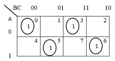
Based on the provided truth table for odd parity, the simplified expression for the parity bit is derived as
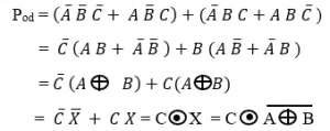
Below is the schematic representation of the odd parity generator circuit.
In this manner, the odd parity generator produces an odd count of 1s based on the input data.
What is Parity Check?
Description: Serving as the receiver's combinational circuit, the parity checker examines the received message, inclusive of the parity bit. It yields a '1' output upon detecting errors and a '0' output when no errors are detected in the message, including the parity bit.
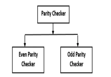
Varieties of Parity Checker
The categorization of the parity checker is illustrated in the figure below.
Even Parity Checker
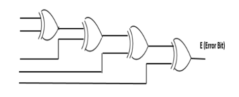
In the even parity checker, the presence of an error is indicated when the error bit (E) equals '1'. Conversely, an error-free transmission is signified by the error bit (E) being '0'.
Error Bit (E) = 1: Error Detected
Error Bit (E) = 0: No Error Detected
The schematic representation of the parity checker circuit is depicted in the figure below.
Odd Parity Checker
In the odd parity checker, a '1' error bit (E) indicates the presence of an error, while an error-free transmission is denoted by an error bit (E) of '0'.
Error Bit (E) = 1: No Error Detected
Error Bit (E) = 0: Error Detected
However, it's important to note that the parity checker is incapable of detecting errors involving more than one bit, and correcting data in such scenarios is not feasible, representing the primary drawbacks of this method.
Parity Generator/Checker using Integrated Circuits (ICs)
The IC 74180 is capable of both generating and checking parity. Below is the schematic representation of a 9-bit parity generator/checker, comprising 8 data bits and 1 parity bit.
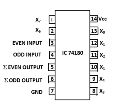
The IC 74180 incorporates eight data bits (X0 to X7), Vcc, even input, odd input, seven outputs, S odd output, and ground pins.
When both the even and odd inputs are set to high (H), the outputs for both even and odd become low (L). Likewise, if both inputs are low (L), the outputs for both even and odd become high (H).
Benefits of Parity
The benefits of employing parity include:
- Simplicity
- User-friendliness
Applications of Parity
Parity finds application in various domains, including:
- Digital systems and numerous hardware implementations
- Utilization in the Small Computer System Interface (SCSI) and Peripheral Component Interconnect (PCI) for error detection
FAQs
1) What distinguishes the parity generator from the parity checker?
The parity generator is responsible for generating the parity bit during transmission, while the parity checker verifies the parity bit upon reception.
2) What does "no parity" signify?
"No parity" or non-parity indicates the absence of parity bit usage for error checking.
3) What constitutes the parity value?
The term "parity value" pertains to commodities and securities, signifying when the values of two assets are equivalent.
4) Why is a parity checker necessary?
A parity checker is essential for error detection during communication and is also employed in memory storage devices for testing purposes.
5) How does the parity bit detect a corrupted data unit?
The redundant bit, known as the parity bit, identifies corrupted data units when errors occur during data transmission.
This article provides insights into how parity generators and checkers operate, including their types, logic circuits, truth tables, and K-map expressions. Here's a question for you: What methods do you use to calculate even and odd parity?
Related Articles
Sawtooth Wave Generator: Design, Construction and Working Principles


