


What is a Square Wave Generator : All Explained
Michael Faraday (September 22nd, 1971 - August 25th, 1867) is credited as the progenitor of the generator. A square wave generator, a variant used for generating square waveforms, employs Schmitt trigger inverters such as TTL for its construction. These generators find utility in signal processing and electronics. Among various generator types, the square wave generator stands out. This article provides an overview of the square wave generator, encompassing its definition, circuitry, and the derivation of its time period and frequency.
What is a Square Wave Generator?
A square wave generator serves as an oscillator that produces output devoid of input, operating on an impulse input within a negligible time frame. Widely employed in digital signal processing and electronic realms, this generator is also referred to as Astable Multivibrator or free-running. Remarkably, the frequency of the square wave generator remains unaffected by the output voltage. Below, we delve into the fundamental circuitry and functionality of this device.
Square Wave Generator Circuit

To devise a square wave generator, a combination of capacitor, resistor, operational amplifier, and power supply is essential. Integrating the capacitor and resistor with the inverting terminal of the operational amplifier, while linking resistors R1 and R2 with the non-inverting terminal, forms the crux of the circuitry. The schematic of a square wave generator utilizing an operational amplifier is elucidated below.
By driving the operational amplifier's output to oscillate between its highest positive voltage (positive saturation) and its lowest negative voltage (negative saturation), we can create a square wave output signal. In theory, with no input voltage present, the output should be zero volts. This is written as Vout (output voltage) = 0 V when Vin (input voltage) = 0 V.
However, in real-world applications, there will likely be a small non-zero output voltage, represented as Vout ≠ 0.
Resistors R1 and R2 form a potential divider circuit. If the initial output voltage is not zero, a voltage will appear across Vb. This creates a positive voltage at both the inverting and non-inverting terminals. The op-amp then amplifies this voltage by its gain, causing the output to swing to its maximum positive voltage, generating one half of the square wave as illustrated in Figure (a).
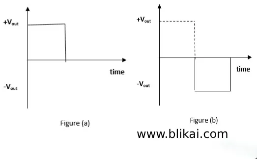
The capacitor initiates its charging cycle once a non-zero input is detected at the inverting terminal. Its voltage gradually increases until it surpasses Vb. Once Vc exceeds Vb (Vc > Vb), the inverting input overtakes the non-inverting input, prompting the op-amp output to transition to negative voltage. This negative voltage is then amplified until it reaches (–Vout)max, resulting in the generation of the negative half of the square wave, as depicted in figure (b). This exemplifies the utilization of an op-amp as a square wave generator.
Derivation of Time Period and Frequency for Square Wave Generator
In the provided circuit diagram, V2 represents the voltage across the capacitor, while V1 denotes the node voltage at the positive terminal. Due to the ideal attributes of the op-amp, the current passing through it is negligible. Let's analyze the node equations derived from the circuit diagram.
V1– V0 / R2 + V1 / R1 = 0
V1 [1/R2 + 1/ R1] = V0 / R2
V1 [R1+ R2 / R1 R2] = V0 / R2
V1(α) = V0 ………… eq (1)
Let’s define
α= R1+ R2 / R1 = 1+ R2 / R1>1
thus, α>1 and V0>1
If V0 = + Vsat
V1 = V0 / α= + Vsat / α= + V1
When V0 = -Vsat
V1 = – Vsat / α= -V1
The voltage V1 exhibits only two states: +V1 and –V1, meaning whenever V0 changes, V1 follows suit. Now, let's examine the behavior of V2. V2 undergoes charging and discharging when we establish a node equation, where the current through a capacitor equals the current.
C d/dt (0- V2) = V2 – V0 / R
-C d V2/dt = V2 – V0 / R
d V2/ V0 – V2 = dt / RC
Upon solving the above equation, we find:
∫0V2 d (V2/V0 -V2 ) = ∫0t dt/RC
Initially, assuming the voltage across the capacitor is zero:
-log (V0 – V2) = t / RC + K
log (V0 – V2) = -t / RC + K
V0 – V2 = K e-t/RC ………… eq (2)
Substituting t=0, V2 = 0 in the above equation, we obtain:
K = V0 …………………………… eq (3)
Where e0 = 1
Substitute eq (3) in eq (2), we get:
V0 – V2 = K e-t/RC
V2 = V0 – V0 e-t/RC
V2 = V0 [1-e-t/RC]
Applying initial conditions:
Stage 1: Let V2 = 0, V0 = +Vsat
In stage-1, V2 charges up to +V1
Stage 2: Let V2 = 0, V0 = -Vsat
In stage-2, V2 discharges up to -V1
[ log (V0 + V1 / V0 – V1)] = 1/RC [T/2]
[ log (αV1 +V2 / αV1 – V1 )] = 1/RC [T/2]………………eq(4)
Substitute eq (1) in eq (4), we find:
log [V1 (α + 1 ) / V1 (α – 1)] = [T/2 RC]
log[((R1+R2/ R1) +1)/( (R1+R2/ R1) -1)] = T/2 RC
log[R1+R2 + R1/ R1+ R2– R1] = T/2 RC
log[2R1+R2 / R1] = T/2 RC
T = 2 RC log[2R1+R2 / R1]……… eq (5)
f = 1 / T
= 1/ 2 RC log[2R1+R2 / R1] ……… eq (6)
Equations (5) and (6) represent the time period and frequency of the square wave generator.
Function Generator Circuit
The function generator serves as a versatile tool designed to produce various waveforms such as sinusoidal, triangular, rectangular, sawtooth, and square waves. These waveforms encompass a range of frequencies, adjustable from fractions of Hertz to several hundred kiloHertz, courtesy of the function generator. Notably, this generator possesses the capability to concurrently generate diverse waveforms for different applications. Below is the circuit diagram depicting the function generator utilizing the LM1458.
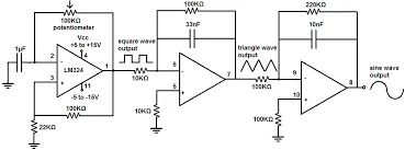
The LM1458 operational amplifier serves dual functions, with shared bias network and power supply lines for both operational amplifiers. Within the function generator circuit, four integrated circuits labeled IC 1a, IC 1b, IC 2a, and IC 2b are utilized. IC 1a functions as an astable multivibrator, IC 1b as an integrator, and IC 2a also operates as an integrator.
In the realm of function generators from 2020, noteworthy models include the GM Instek SFG-1013 DOS, DIY Function Generator Kit by JYE Tech FG085, ATTEN ATF20B DDS, Rigol DGI02220 MHz Function Generator featuring a secondary channel, Eisco Labs Function Generator with a frequency range of 1KHz to 100 kHz, B & K Precision 4011A Function Generator, JYETech 08503 – Portable Digital Function Generator, Tektronix AFG1062 Arbitrary Function Generator, Keithley 3390 Arbitrary Function Generator, and Rigol DG1062Z Function/Arbitrary Waveform Generator.
Advantages
The advantages of the square wave generator include:
1. Simplicity
2. Ease of maintenance
3. Cost-effectiveness
Frequently Asked Questions (FAQs)
1. What are square waves?
Square waves are grid-like patterns that appear on the surface of the ocean, also referred to as cross waves or cross-sea waves.
2. What are the various types of signal generators?
Signal generators come in different types, including:
- Frequency Generator
- Arbitrary Waveform Generator
- Microwave and RF Function Generators
- Pitch Generator
- Digital Pattern Generators
3. What are the various categories of multivibrator circuits?
There exist three categories of multivibrator circuits: Monostable Multivibrator Circuit, Astable Multivibrator Circuit, and Bistable Multivibrator Circuit.
4. What defines a function generator?
A function generator refers to a device utilized for producing electrical waveforms across a broad frequency spectrum. The waveforms generated by such equipment encompass triangular waves, square waves, sine waves, and sawtooth waves.
5. What risks are associated with square waves?
While square waves may appear captivating, they pose hazards to swimmers and boats. When two wave systems intersect, they create patterns resembling squares on the ocean's surface, which can be perilous.
In this articles, we delve into the benefits of square wave generators, explore circuit diagrams for square wave generators, and examine function generators. Now, a question for you: What is your recommendation for the top square wave generator on the market?


