


Exploring Varied Types of Inverters
Electricity, primarily delivered as Alternating Current (AC), serves as the predominant power source for residential, commercial, and industrial applications. However, AC faces a significant limitation – it cannot be stored for future use. To overcome this, the solution involves converting AC to Direct Current (DC), which can be stored in batteries and ultra-capacitors. When AC power is required again, the stored DC is transformed back into AC through a device known as an inverter. In essence, an inverter is a crucial tool that converts DC to variable AC, allowing for adjustments in voltage magnitude, phase numbers, frequency, or phase differences as needed.
Inverter and types of inverters
(I)Based on Output Characteristics
Inverters can be categorized into three types based on their output characteristics:
Square Wave Inverter
This inverter produces a square wave as the output waveform of the voltage. However, it is the least utilized type due to compatibility issues. Most appliances are designed for a sine wave power supply, and using a square wave may lead to damage or high losses. Despite its low cost, its application is rare and is typically limited to simple tools with universal motors.
Sine Wave Inverter
The output waveform of this inverter is a sine wave, closely resembling the utility supply. This type holds a significant advantage as it provides an output suitable for appliances designed for sine wave input. Although more expensive, sine wave inverters are extensively used in residential and commercial applications, ensuring proper functionality of equipment.
Modified Sine Wave Inverter
Comparatively more complex than a square wave inverter but simpler than a pure sine wave inverter, the modified sine wave inverter produces an output that is a combination of two square waves. Although not an exact sine wave, the waveform closely resembles the shape of a sine wave. The construction complexity falls between the square wave and pure sine wave inverters.
(II) Based on the Inverter Source
Inverters can be classified into two types based on their source:
Current Source Inverter (CSI)
In CSI, the input is a current source. This inverter type finds application in medium-voltage industrial settings where high-quality current waveforms are essential. However, CSIs are not widely popular.
Voltage Source Inverter (VSI)
In VSI, the input is a voltage source. This type of inverter is utilized in various applications due to its higher efficiency, increased reliability, and faster dynamic response. VSIs are capable of running motors without de-rating.
(III) According to Load Type
Inverters can be categorized based on the type of load they serve:
Single-phase Inverter
Residential and commercial loads often use single-phase power, and the single-phase inverter is designed for such applications. This category further divides into:
A) Single Phase Half-bridge Inverter
This inverter type comprises two thyristors and two diodes.
In this scenario, the total DC voltage is denoted as Vs and is evenly divided into two equal parts, Vs/2. The time for one cycle is T seconds.
During the first half cycle (0 < t < T/2), thyristor T1 conducts, resulting in a load voltage of Vs/2 due to the upper voltage source Vs/2.
In the second half cycle (T/2 < t < T), thyristor T1 is commutated, and T2 conducts. In this period, the load voltage becomes -Vs/2 due to the lower source Vs/2. This operation generates an alternating voltage waveform with a frequency of 1/T Hz and a peak amplitude of Vs/2. The output waveform initially appears as a square wave, which is then passed through a filter to eliminate unwanted harmonics, resulting in a pure sine waveform. The frequency of the waveform can be controlled by adjusting the ON time (Ton) and OFF time (Toff) of the thyristor.
The magnitude of the output voltage is half of the supply voltage, and the source utilization period is 50%. This represents a drawback of the half-bridge inverter, and the solution to this limitation is the full-bridge inverter.
B) Single Phase Full-bridge Inverter
In this type of inverter, four thyristors and four diodes are employed. During the first half cycle (0 < t < T/2), two thyristors T1 and T2 conduct, resulting in a load voltage of Vs, similar to the DC supply voltage.
For the second half cycle (T/2 < t < T), two thyristors T3 and T4 conduct, leading to a load voltage of -Vs during this period.
In this configuration, the AC output voltage matches the DC supply voltage, achieving a source utilization factor of 100%. The output voltage waveform is square, and filters are employed to transform it into a sine wave.
If all thyristors conduct simultaneously or in pairs (T1 and T3) or (T2 and T4), a short circuit will occur in the source. Diodes are incorporated in the circuit as feedback diodes, facilitating energy feedback to the DC source.
Comparing the full-bridge inverter with the half-bridge inverter, for a given DC supply voltage load, the output voltage is doubled, and the output power is quadrupled in the full-bridge inverter.
Three-Phase Bridge Inverter
For industrial loads requiring a three-phase AC supply, a three-phase inverter is utilized. In this type of inverter, six thyristors and six diodes are employed and connected .
It can operate in two modes based on the degree of gate pulses:
180-degree mode
120-degree mode
(IV) Classification According to Control Technique
- Single Pulse Width Modulation (single PWM)
- Multiple Pulse Width Modulation (MPWM)
- Sinusoidal Pulse Width Modulation (SPWM)
- Modified Sinusoidal Pulse Width Modulation (MSPWM)
The inverter produces a square wave signal as its output, which is not directly used for the load. The control of the AC output voltage is achieved through Pulse Width Modulation (PWM) techniques. PWM controls the ON and OFF periods of switches to regulate the output voltage. This control is accomplished using two signals: a reference signal and a triangular carrier signal. Gate pulses for the switches are generated by comparing these two signals, and various PWM techniques are employed.
Single Pulse Width Modulation (single PWM)
In this control technique, only one pulse is available for each half cycle. The reference signal is a square wave, and the carrier signal is a triangular wave. Gate pulses for the switches are generated by comparing these signals. The output frequency is controlled by the frequency of the reference signal, and the modulation index is defined as Ar/Ac, where Ar is the amplitude of the reference signal, and Ac is the amplitude of the carrier signal. A drawback of this technique is its high harmonic content.
Multiple Pulse Width Modulation (MPWM)
To address the drawbacks of single PWM, multiple PWM is employed. Instead of one pulse, several pulses are used in each half cycle of the output voltage. Gate pulses are generated by comparing the reference and carrier signals. The output frequency is controlled by adjusting the carrier signal's frequency. The modulation index is used for controlling the output voltage, and the number of pulses per half cycle is determined by fc/(2*f0), where fc is the frequency of the carrier signal, and f0 is the frequency of the output signal.
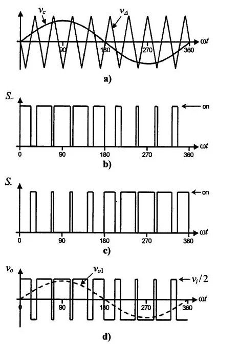
Sinusoidal Pulse Width Modulation (SPWM)
This control technique finds extensive use in industrial applications. In contrast to the previous methods where the reference signal is a square wave, SPWM employs a sine wave as the reference signal. The gate pulses for the switches are generated by comparing the sine wave reference signal with the triangular carrier wave. The width of each pulse varies with changes in the amplitude of the sine wave. The frequency of the output waveform aligns with the frequency of the reference signal. The resulting output voltage is a sine wave, and the RMS voltage can be controlled through the modulation index. Refer to the waveforms illustrated in the figure below for a visual representation.
Modified Sinusoidal Pulse Width Modulation (MSPWM)
In the SPWM technique, the pulse width of the waveform remains unaltered with changes in the modulation index due to the nature of the sine wave. To address this limitation, the MSPWM technique was introduced. In this approach, the carrier signal is applied during the first and last 60-degree intervals of each half cycle. This modification enhances its harmonic characteristics. The key advantages of MSPWM include an increased fundamental component, a reduced number of switching power devices, and diminished switching loss.
(V) According to the Number of Levels at the Output
- Regular Two-Level Inverter
- Multi-level Inverter
Regular Two-Level Inverter
These inverters exhibit only two voltage levels at the output, representing the positive peak voltage and negative peak voltage. Occasionally, having a zero-voltage level is also recognized as a two-level inverter.
Multilevel Inverters
These inverters can feature multiple voltage levels at the output. The multi-level inverter is categorized into four types:
- Flying Capacitor Inverter
- Diode-Clamped Inverter
- Hybrid Inverter
- Cascade H-Type Inverter
Each type of inverter has its unique design and operational characteristics, providing a basic understanding of their distinctions.


