


DC Machine : Construction & Its Principle
It seems like you have a good understanding of DC machines! Just a small correction: while DC machines do use a commutator to convert AC voltage to DC voltage, they don't actually include AC currents or voltages within them. Instead, they convert the alternating current generated within the machine to direct current through the action of the commutator.
Also, the application of DC machines extends beyond trains, mills, and mines. They are still widely used in various industries and applications where precise speed control and torque regulation are required, such as in paper mills, steel mills, cranes, and machine tools. Additionally, while DC dynamos were indeed used in the past for charging automobile batteries, modern automobiles typically use alternators, which are a type of AC generator.
What constitutes a DC Machine?
A DC apparatus is an electro-mechanical device that transforms energy. Its operational principle hinges on the flow of electric current through a coil within a magnetic field, resulting in a magnetic force that induces torque, driving the DC motor's rotation. DC machines are categorized into two forms: DC generators and DC motors.
DC Machine
The primary purpose of a DC generator is to transform mechanical energy into DC electrical power, while a DC motor does the opposite, converting DC power into mechanical power. In industrial settings, AC motors are commonly employed to convert electrical energy into mechanical energy. Conversely, DC motors are preferred in applications requiring precise speed control and a broad range of speeds, such as electric-transaction systems.
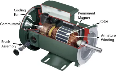
Structure of DC Machine
Assembling a DC machine involves key components including the Yoke, Pole Core & Pole Shoes, Field Coil & Pole Coil, Armature Core, Armature Winding or Conductor, Commutator, Brushes, and Bearings. Further details regarding the components of a DC machine are outlined below.

Structure of DC Machine
Yoke (Frame)
The yoke, also known as the frame, serves the primary function of providing mechanical support for the poles while shielding the entire apparatus from environmental elements such as moisture and dust. Typically constructed from materials such as cast iron, cast steel, or rolled steel.
Pole and Pole Core
In a DC machine, the pole functions as an electromagnet, with the field winding situated around it. When the field winding is energized, the pole generates magnetic flux. Materials commonly used for poles include cast steel, cast iron, or pole cores, which can be constructed using annealed steel laminations to mitigate power loss due to eddy currents.
Pole Shoe
The pole shoe within a DC machine serves as an expansive component, enlarging the pole's area. This expansion facilitates the dispersion of flux across the air-gap, allowing additional flux to permeate through to the armature. Typically constructed from materials such as cast iron or cast steel, pole shoes may also incorporate annealed steel laminations to minimize power loss due to eddy currents.
Field Windings
In the realm of DC machines, the windings enveloping the pole core are referred to as field coils. When current flows through these windings, they magnetize the poles, generating the necessary flux. Copper is the predominant material used for constructing field windings.
Armature Core
The armature core is characterized by a multitude of slots along its circumference, housing the armature conductor. This arrangement offers a low-reluctance pathway for the flux generated by the field winding. Typically composed of materials with low reluctance and high permeability, such as iron or cast materials, armature cores often incorporate laminations to mitigate losses stemming from eddy currents.
Armature Winding
The armature winding is crafted by interconnecting armature conductors. When propelled by a prime mover, this winding induces voltage and magnetic flux within it. It is linked to an external circuit and typically composed of conducting materials such as copper.
Commutator
In the realm of DC machines, the commutator serves the crucial role of collecting current from the armature conductor and delivering it to the load via brushes. It also facilitates the generation of uni-directional torque for DC motors. Constructed with numerous segments made of hard drawn copper arranged in an edge format, the commutator segments are shielded by a thin layer of mica.
Brushes
Brushes within a DC machine are responsible for retrieving current from the commutator and transmitting it to the external load. Over time, brushes wear down and require frequent inspection. Typically made of graphite or carbon in rectangular form, brushes play a vital role in maintaining electrical contact within the machine.
Types of DC Machines
DC machines are categorized based on their excitation method and winding configurations. The two main types of excitation are separate excitation and self-excitation.
1. Separate Excitation:
In this type of DC machine, the field coils are energized by a separate DC source.
2. Self-Excitation:
Here, the field winding is energized by the machine itself, without the need for an external DC source.
The primary classifications of DC machines are as follows:
1. Separately Excited DC Machine:
Utilizes a separate DC source to energize the field coils.
2. Shunt Wound (Shunt Machine):
The field coils are connected in parallel with the armature. Typically consists of a large number of turns of fine wire to carry a small field current.
3. Series Wound (Series Machine):
The field coils are connected in series with the armature. Suitable for applications requiring high starting torque.
4. Compound Wound (Compound Machine):
Combines both series and shunt winding configurations to achieve desired performance characteristics, such as improved speed regulation and starting torque.
Each type of DC machine has distinct characteristics and applications, making them suitable for various industrial and commercial purposes.
Series Wound:
In series-wound DC machines, the field coils are connected in series with the armature. Because the series field winding carries the full armature current, which is typically high, it is constructed with fewer turns of wire of larger cross-sectional area.
Compound Wound:
A compound machine combines both series and shunt field windings. Each machine pole carries both types of windings. The series winding is composed of a few turns of wire with a large cross-sectional area, while the shunt winding consists of numerous fine wire turns.
Compound machines can be connected in two ways:
1. Short Shunt Compound Machine:
In this configuration, the shunt field is connected in parallel with the armature only.
2. Long Shunt Compound Machine:
Here, the shunt field is connected in parallel with both the armature and the series field.
EMF Equation of DC Machine:
The electromotive force (EMF) of a DC machine arises as the armature rotates, inducing voltage in its coils. In a generator, this rotational EMF is termed the generated EMF (Eg), while in a motor, it's referred to as the counter or back EMF (Eb). Let's break down the components of the EMF equation:
- Φ represents the useful flux per pole in webers.
- P denotes the total number of poles.
- z signifies the total number of conductors in the armature.
- n represents the armature rotation speed in revolutions per second.
- A denotes the number of parallel paths across the armature between opposite polarity brushes.
- Z/A is the number of armature conductors in series per parallel path.
During each revolution, every conductor cuts a flux of PΦ. The voltage induced per conductor is the flux cut per revolution in webers divided by the time taken for one revolution in seconds.
Since n revolutions occur in one second and one revolution takes 1/n seconds, the time for one armature revolution is 1/n seconds.
The standard value of induced voltage per conductor is pΦ / (1/n) = npΦ volts.
The total induced voltage (E) is determined by the number of armature conductors in series in any single path between the brushes. Therefore, the overall induced voltage is calculated as:
E = standard voltage per conductor × number of conductors in series per path
E = nPΦ × Z/A
This equation represents the EMF equation of the DC machine.
DC Machine Vs AC Machine:
The distinction between AC motors and DC motors encompasses several key differences:
|
AC Motor |
DC Motor |
| An AC motor is an electrical apparatus that functions by utilizing alternating current (AC) as its power source. | A DC motor is a type of rotary motor designed to convert electrical energy from direct current (DC) into mechanical motion. |
| These are categorized into two types: synchronous and induction motors. | These motors are available in two types: brushed and brushless motors. |
| The AC motor is powered by an alternating current input supply. | The DC motor operates using a direct current input supply. |
| In this motor, brushes and commutators are absent. | In this motor, carbon brushes and commutators are included. |
| AC motors can be powered by both single-phase and three-phase input supplies. | DC motors are typically powered by single-phase direct current (DC) input supplies. |
| The armature characteristics of AC motors involve the armature remaining inactive while the magnetic field rotates. | The armature characteristics of DC motors involve the armature rotating while the magnetic field remains stationary. |
| It possesses three input terminals labeled R, Y, and B, corresponding to the phases of the electrical supply. | It features two input terminals, typically designated as positive and negative, for the direct current power supply. |
| Speed control of AC motors can be achieved by adjusting the frequency of the input power supply. | The speed of a DC motor can be controlled by adjusting the current flowing through the armature winding. |
| The efficiency of an AC motor may be lower due to losses incurred from induction current and motor slip. | The efficiency of a DC motor tends to be higher because it does not experience induction current or slip, factors that can contribute to energy losses in AC motors. |
| It doesn’t need any maintenance | It needs maintenance |
| AC motors are employed in applications requiring high speed and variable torque. | DC motors find application in scenarios necessitating variable speed and high torque. |
| In practice, both AC and DC motors find extensive use in large industries. | In practical applications, both AC and DC motors are utilized in various appliances. |
Losses in DC Machine:
During the conversion of mechanical energy to electrical energy in a DC machine, not all input power is transformed into output power due to losses occurring in various forms. These losses vary between different types of machines and contribute to decreased efficiency and increased temperature. The losses in a DC machine can be categorized as follows:
1. Electrical or Copper Losses: Occur due to the resistance of the armature winding and field winding, resulting in power dissipation in the form of heat.
2. Core Losses or Iron Losses: Result from hysteresis and eddy current losses in the core materials of the machine, leading to heat generation.
3. Mechanical Losses: Arise from friction and windage losses within the machine, including losses in bearings, gears, and brushes.
4. Brush Losses: Occur due to the friction and electrical resistance at the brush-commutator interface, resulting in heat dissipation.
5. Stray Load Losses: Stem from the leakage flux and parasitic losses in the machine, leading to additional power dissipation.
Advantages of DC Machine:
DC machines, particularly DC motors, offer several advantages:
1. High Starting Torque: DC motors provide high starting torque, making them suitable for applications requiring rapid acceleration.
2. Reversibility: DC motors can easily reverse direction, allowing for bidirectional operation.
3. Fast Starting and Stopping: DC motors can start and stop quickly, enhancing operational efficiency and control.
4. Variable Speed Control: Speed control in DC motors is easily achieved by adjusting the applied voltage, enabling precise speed regulation.
5. High Torque: DC motors can provide high torque at low speeds, making them suitable for applications requiring high torque output.
6. Seamless Operation: DC motors operate smoothly and efficiently, with minimal vibration and noise.
7. Free from Harmonics: Unlike some types of AC motors, DC motors do not produce harmonics, simplifying power quality considerations.
8. Easy Installation and Maintenance: DC machines are relatively simple to install and maintain, with fewer components compared to some AC machines.
Overall, the advantages of DC machines make them well-suited for a wide range of industrial and commercial applications where precise speed control, high torque, and seamless operation are required.
The detailed breakdown of DC machine applications provides valuable insights into their utilization across various industries and processes. While AC is commonly generated in bulk, DC machines still play crucial roles in specific applications, particularly where precise control and characteristics are required.
DC generators, although limited in application compared to AC generators, are indispensable for providing excitation to small and medium-sized alternators. Industries rely on DC machines for processes such as welding and electrolysis.
In many cases, AC generated is rectified into DC using rectifiers for various applications. DC motors find extensive use in variable speed drives and applications where abrupt changes in torque are common.
DC motors are classified into three main types based on their application: series, shunt, and compound motors. Similarly, DC generators are categorized into separately excited, series, and shunt-wound generators.
In summary
DC machines encompass both DC generators and DC motors. DC generators primarily supply DC power to other DC machines in power stations, while DC motors drive a plethora of devices across industries, including lathes, fans, pumps, printing presses, locomotives, hoists, cranes, conveyors, mills, auto-rickshaws, and ice machines.
Now, to answer your question, commutation in a DC machine refers to the process by which the direction of current flow in the armature windings is switched as the rotor rotates, ensuring continuous and unidirectional rotation of the motor. This process is facilitated by the commutator and brushes, which maintain electrical contact with the armature windings and reverse the current direction at the appropriate moment to maintain torque production and smooth operation.
Related Articles
Multimeter Not Reading DC Voltage: How to Fix it?
Comparative Analysis of DC Transmission and AC Power


