


What does Comparator Do?
Evaluating two or more data items to ascertain their equality or establish the size relationship and arrangement order is termed comparison. A circuit or device capable of performing this comparison function is known as a comparator.
Ⅰ.Principle of comparator
A comparator functions as a circuit that contrasts an analog voltage signal against a reference voltage. Its inputs are analog signals, and the output manifests as a binary signal, 0 or 1. When the input voltage difference alters, and the sign remains consistent, the output remains steady.
The comparator, in principle, can serve as a 1-bit analog-to-digital converter (ADC). Although an operational amplifier can act as a comparator when devoid of negative feedback, its usage is limited due to its high open-loop gain, restricting it to minute input differential voltages. Operational amplifiers also exhibit extended delay times, which may not align with practical requirements. While comparators can be fine-tuned for minimal time delays, their frequency response may be constrained. To prevent output oscillation, many comparators integrate internal hysteresis circuits. The comparator's threshold, which may have one or two fixed values, plays a pivotal role.
Ⅱ.Performance of comparator
Hysteresis Voltage: This voltage, situated between the comparator's two input terminals, induces a change in output state upon crossing zero. As input terminals often encounter slight fluctuation voltages, the resultant differential mode voltage from these fluctuations can lead to continuous changes in the comparator's output. To forestall output oscillation, contemporary comparators are typically endowed with a hysteresis voltage of several millivolts. The hysteresis voltage introduces two switching points in the comparator: one for detecting rising voltage and the other for detecting falling voltage. The discrepancy in voltage threshold (VTRIP) equals the hysteresis voltage (VHYST). The offset voltage of a hysteresis comparator is the average of TRIP and VTRIP-. In contrast, a comparator lacking hysteresis designates its input voltage switching point as the input offset voltage, deviating from the ideal comparator's zero voltage. The offset voltage tends to fluctuate with temperature and power supply voltage, often expressed through the power supply rejection ratio to denote the impact of power supply voltage variations on the offset voltage.
Bias Current
Theoretical ideal comparators possess infinite input impedance, ensuring no impact on the input signal. However, real comparators deviate as their input impedance cannot be infinite. A current flows through the internal resistance of the signal source into the comparator's input, creating an additional pressure difference. Bias current (Ibias) signifies the median of the input currents of two comparators, gauging the effect on input impedance. The MAX917 series of comparators boasts a maximum bias current of merely 2nA.
Super Power Swing
Maxim employs a parallel NPN and PNP tube structure as the input stage of the comparator to optimize its operating voltage range. This design choice expands the input voltage range, allowing the lower limit to be the lowest level and the upper limit to reach 250mV higher than the power supply voltage, achieving the Beyond-the-Rail standard. This design also permits a larger common-mode voltage at the input terminal of the comparator.
Drain-Source Voltage
With only two distinct output states (zero level or power supply voltage), the output stage of a full power swing comparator is an emitter follower. Consequently, there is a minimal pressure difference between its input and output signals. The voltage difference hinges on the emitter junction voltage in the saturation state of the internal transistor, corresponding to the drain-source voltage of the MOSFET.
Output Delay Time
Encompassing signal transmission delay through components and signal rise and fall times, output delay time is a critical parameter. High-speed comparators like MAX961 exhibit a typical delay time of 4.5ns and a rise time of 2.3ns. When designing, meticulous attention is necessary to account for various factors influencing delay time, including temperature, capacitive load, and input overdrive.
Ⅲ.Classification of comparator
Zero-Crossing Voltage Comparator: An archetype amplitude comparison circuit, its circuit diagram, and transmission characteristic curve are depicted in the figure.
Voltage Comparator
Transforming an input terminal of the zero-crossing comparator from ground to a fixed voltage yields a voltage comparator. Figure illustrates its circuit diagram and transmission characteristic curve.
Window Comparator
Constructed with two amplitude comparators, diodes, and resistors, the window comparator's circuit and transmission characteristics are depicted in Figure. If the high-level signal potential surpasses a specified value VH, it mimics the positive saturation output. Conversely, when the low-level signal potential drops below a defined value VL, it resembles the negative saturation output. With dual thresholds, the transmission characteristic curve assumes a window shape, earning it the name "window comparator."
Hysteresis Comparator
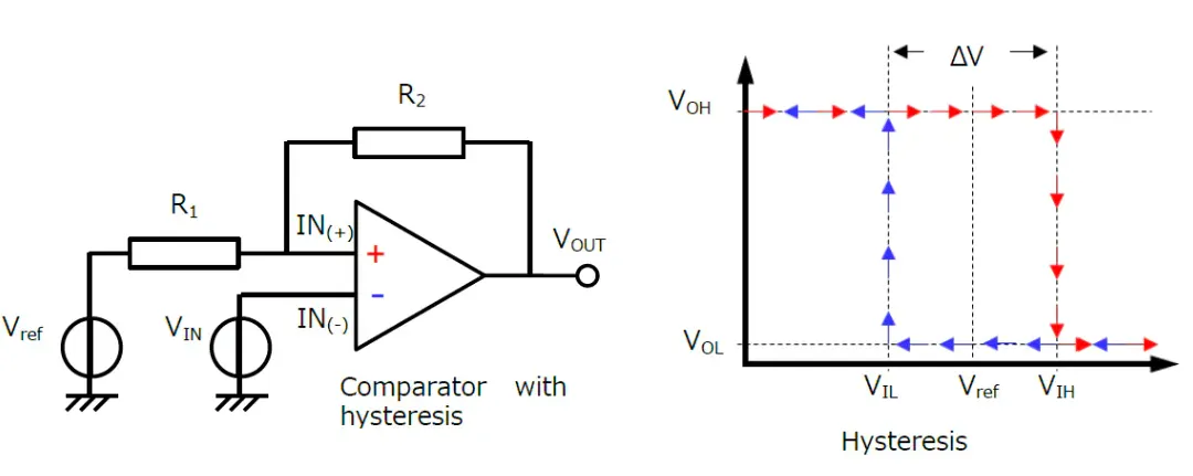
Incorporating a resistor divider branch from the output to the non-inverting input, the hysteresis comparator's circuit and transmission characteristics are illustrated in Figure. As the input voltage vI rises from zero and VI remains below VT, the comparator produces a positive saturation voltage, where VT denotes the upper threshold (trigger) level. On the contrary, when the input voltage VI surpasses VT', the comparator yields a negative saturation voltage, with VT' denoting the lower threshold (trigger) level.
Ⅳ.Application of comparator
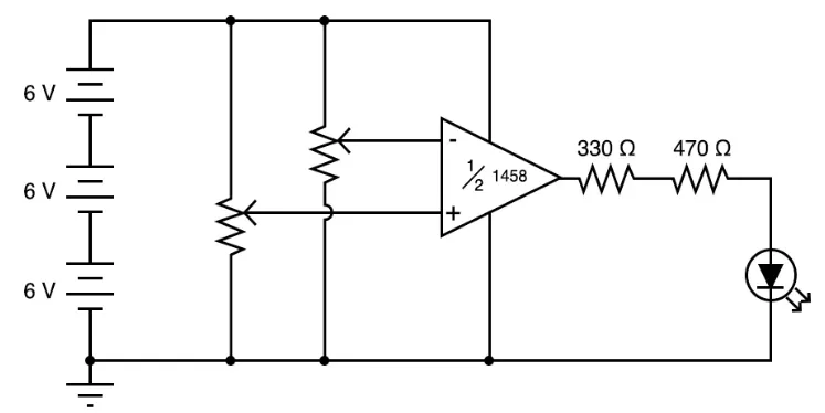
Incorporating four comparators in a current detection circuit facilitates the indication of four states of the input current. Utilizing the "Shunt" resistor transforms the input current into a voltage signal. R1 and R2, serving as comparators, set the operational amplifier's gain and provide necessary reference voltages. R4 ~ R7 establish detection thresholds for different digital output states.
Zero-Crossing Comparator
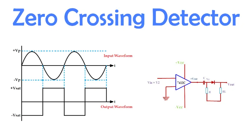
This comparator identifies whether an input value is zero. The principle involves comparing two input voltages using a comparator: the reference voltage (Vr) and the measured voltage (Vu). Outputting forward or reverse saturation voltage based on the comparison result indicates whether the reference voltage is zero, thus defining a zero-crossing comparator.
Relaxation Oscillator
Comparators contribute to constructing relaxation oscillators, combining positive feedback (Schmitt trigger) and negative feedback (RC circuit). This setup transforms the circuit from a latch to a relaxation oscillator, enabling spontaneous oscillation.
Level Shifting
Open-drain comparators like LM393, TLV3011, and MAX9028 form level shifters for signal voltage conversion. Tailoring the pull-up voltage allows flexible adjustment of the converted voltage value, for instance, using the MAX972 to convert ±5V signals into 3V signals.
Analog to Digital Converter
Comparators play a pivotal role in analog-to-digital conversion by quantizing input analog signals. Various digital-to-analog converters, including delta-sigma modulation, incorporate comparators for this quantization process.
Ⅴ.Voltage Comparator
A voltage comparator, resembling an operational amplifier with an amplification factor nearing "infinity," compares the magnitudes of two voltages. Its output voltage levels, high or low, indicate the relationship between the input voltages. When the voltage at the "+" input surpasses that at the "-" input, the output is high; when the "+" input voltage is lower, the output is low.
Role of Voltage Comparator
Acting as an interface between analog and digital circuits, voltage comparators find use in waveform generation and conversion circuits. They can transform sine waves into square or rectangular waves with matching frequencies. While simple voltage comparators boast a straightforward structure and high sensitivity, their susceptibility to interference necessitates improvements. Enhanced versions, such as hysteresis comparators and window comparators, have been developed.
Operational Amplifiers and Voltage Comparators
Operational amplifiers, with feedback loops determining operational parameters, can sometimes function as voltage comparators without negative feedback. In these applications, the input is a linear quantity, and the output is a binary switch. Common operational amplifiers suitable for such use include LM324, LM358, uA741, TL081\2\3\4, OP07, and OP27.
Specialized Voltage Comparators
Chips like LM339 and LM393 serve as professional voltage comparators, featuring fast switching speeds and minimal delay times. While designed for specific voltage comparison scenarios, they essentially function as operational amplifiers.


