


Difference Btween Amplifier and Current-Sense Amplifier
Precision high-side current sensing is essential in various applications, such as motor control, solenoid control, and power management, encompassing tasks like dc-to-dc converters and battery monitoring. In these scenarios, monitoring current on the high side, as opposed to the return side, facilitates enhanced diagnostic capabilities, including the detection of ground shorts and continuous monitoring of recirculation-diode current. Additionally, this approach preserves the integrity of the ground path by avoiding the introduction of shunt resistance. Figures 1, 2, and 3 illustrate typical configurations of high-side current shunts for solenoid and motor control.
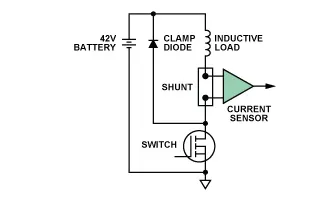
Figure 1. High-side shunt in typical solenoid control.
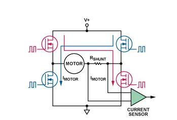
Figure 2. High-side shunt in H-bridge motor control.
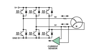
Figure 3. High-side shunts in 3-phase motor control.
Across all depicted configurations, the pulse-width-modulated (PWM) common-mode voltage at the shunt resistor—used to monitor load current—swings throughout the entire range from ground to battery. This PWM input signal is characterized by a period, frequency, and rise/fall time determined by the control signal from the power stage to the FET. Consequently, the difference-measurement circuitry monitoring the voltage across the shunt resistor necessitates a stringent combination of very high common-mode rejection, high-voltage handling capability, as well as high gain, accuracy, and low offset. These attributes are crucial for providing an accurate representation of the load current.
In solenoid control (Figure 1), utilizing a single control FET ensures that the current always flows in the same direction, making a unidirectional current sensor sufficient. For motor control configurations (Figures 2 and 3), placing the shunt on the motor phase implies that current in the shunt resistor could flow in both directions, mandating a bidirectional current sensor.
Designers exploring options for high-side current-sensing will encounter a range of choices from various semiconductor vendors. However, these integrated-circuit devices can broadly be categorized into two high-voltage architectures: current-sense amplifiers and difference amplifiers.
This discussion aims to highlight key distinctions between these architectures, assisting designers in selecting the most suitable device for high-side current sensing in their application. A comparison will be made between two high-voltage components: the AD8206 bidirectional difference amplifier and the AD8210 bidirectional current-sense amplifier. Despite sharing the same pinout, these devices differ in specifications and architectures. Therefore, understanding these differences is essential for choosing the optimal device for a given application.
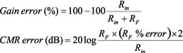
Operation of the AD8206
The AD8206 (depicted in Figure 4) functions as an integrated high-voltage difference amplifier, capable of withstanding common-mode voltages up to 65 V. To achieve this, input resistors are employed to attenuate the input voltage by a factor of 16.7:1, ensuring that the common-mode voltage stays within the input range of amplifier A1. However, this input resistance network also attenuates the differential signal by the same factor. In order to attain the AD8206's featured gain of 20 V/V, both amplifiers A1 and A2 must amplify the differential signal by approximately 334 V/V.
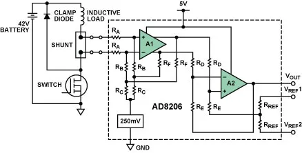
Figure 4. AD8206 simplified schematic.
This device facilitates bidirectional input measurements by offsetting the output amplifier to a suitable voltage within the supply range. The offset is accomplished by applying an external low-impedance voltage to a precisely trimmed resistance divider connected to the positive input of A2. An interesting feature of the AD8206 is its ability to accurately amplify the differential input voltage even when the common-mode voltage goes negative by up to 2 V, a result of the 250-mV common-mode bias circuit illustrated in the figure.
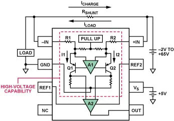
Figure 5. AD8210 functional diagram.
Comparison with the AD8210
The AD8210 (illustrated in Figure 5), a recently introduced high-voltage current-sense amplifier, shares the same pin connections as the AD8206 but operates differently, leading to distinct specifications. Notably, the AD8210's input structure doesn't rely on a resistive attenuation network to handle large common-mode voltage. Instead, its input amplifier incorporates high-voltage transistors, manufactured using the XFCB IC fabrication process. Since the VCE breakdown of all transistors exposed to this voltage exceeds 65 V, the common-mode voltage at the input can reach up to 65 V.
Current-sense amplifiers like the AD8210 amplify the small differential input voltage by connecting the input terminals to the differential amplifier, A1, through resistors R1 and R2. A1 nulls the voltage across its input terminals by adjusting the current through R1 and R2 with transistors Q1 and Q2. The differential currents through Q1 and Q2 are then converted to a ground-referenced differential voltage using internal precision-trimmed resistors. Amplifier A2, utilizing low-voltage transistors powered by the device's 5-V supply, further amplifies this voltage to produce the final output with an overall gain of 20.
Distinguishing Factors and Considerations
It's evident that current-sense amplifiers and difference amplifiers serve the same purpose but operate differently. Difference amplifiers attenuate high input voltages, bringing the signal to a level the amplifier can handle, while current-sense amplifiers convert the differential input voltage to a current and then back to a ground-referenced voltage. The inherent differences between these architectures lead to performance variations that designers must consider when selecting a high-side current-monitoring solution.
Comparing Current Amplification and Differential Amplification Schemes
Key Points to Consider:
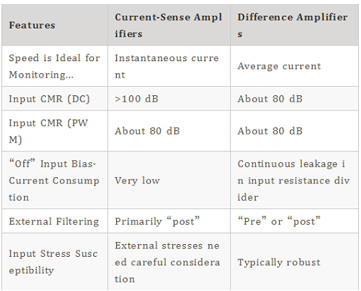
Bandwidth: Due to input attenuation, the bandwidth of difference amplifiers is typically around one-fifth of that of current-sense amplifiers. This is crucial for applications with specific frequency requirements.
Common-Mode Rejection: The input structure differences result in variations in Common-Mode Rejection (CMR) performance. Difference amplifiers often guarantee 80-dB CMR at dc, while current-sense amplifiers can achieve better CMR, particularly at higher common-mode voltages.
Effect of External Input Filtering: The architecture influences the impact of external input filters. Care must be taken when using filters with current-sense amplifiers, as they can introduce gain and CMR errors.
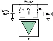
Figure 6. Input filter options.
Overdriving the Inputs: The robustness of the amplifier when subjected to potential events causing it to operate outside its specified range differs between the two architectures. Difference amplifiers are generally more resilient to large voltage swings across the inputs.
Negative Voltage Protection: The resistance-bridge input of difference amplifiers provides a potential survival factor against reversed battery voltage, while current-sense amplifiers may face challenges in this regard.
Input Bias Current: The input structure influences input bias current considerations, especially in applications where power management is critical.
Conclusion
High-side current sensing is essential across various applications, and integrated high-voltage difference and current-sense amplifiers are available to fulfill this role. The choice between the two depends on the specific requirements and constraints of the application, with considerations such as bandwidth, common-mode rejection, external filtering, input overdriving, negative voltage protection, and input bias current being crucial factors. Designers must carefully evaluate these factors to determine the most suitable type of current sensor for their system.
| Features | Current-Sense Amplifiers | Difference Amplifiers |
| Speed is Ideal for Monitoring... | Instantaneous current | Average current |
| Input CMR (DC) | >100 dB | About 80 dB |
| Input CMR (PWM) | About 80 dB | About 80 dB |
| “Off” Input Bias-Current Consumption | Very low | Continuous leakage in input resistance divider |
| External Filtering | Primarily “post” | “Pre” or “post” |
| Input Stress Susceptibility | External stresses need careful consideration | Typically robust |


