


IR Sensors: Schematic and Priciple Explained
In daily life and industrial settings, IR technology serves various functions. For instance, televisions utilize IR sensors to interpret signals transmitted from remote controls. Key advantages of IR sensors include their minimal power consumption, straightforward design, and user-friendly features. Human eyes cannot detect IR signals. Within the electromagnetic spectrum, IR radiation spans from the visible to microwave regions. Typically, these waves have wavelengths ranging from 0.7 µm to 1000µm. The IR spectrum is categorized into three regions: near-infrared (0.75 – 3µm), mid-infrared (3 to 6µm), and far-infrared (wavelengths exceeding 6µm).
Understanding IR Sensors/Infrared Sensors
An infrared sensor, also known as an IR sensor, is an electronic apparatus designed to emit signals for the purpose of detecting various elements in its environment. It can gauge an object's temperature and detect motion. Passive IR sensors, unlike active ones, solely measure infrared radiation without emitting it. Typically, all objects emit some degree of thermal radiation within the infrared spectrum.
Such radiations, imperceptible to the human eye, can be discerned by an infrared sensor. The emitter comprises merely an IR LED (Light Emitting Diode), while the detector consists of an IR photodiode sensitive to IR light of the identical wavelength as emitted by the IR LED. Upon IR light incidence on the photodiode, the resistances and output voltages vary in correspondence with the intensity of received IR light.
Principle of Operation
The operational concept of an infrared sensor closely mirrors that of an object detection sensor. Combining an IR LED with an IR photodiode forms a photosensitive coupling unit, often termed an optocoupler. Fundamental physics principles governing this sensor include Planck's radiation law, Stefan-Boltzmann law, and Wien's displacement law.
An IR LED acts as a transmitter, emitting IR radiation similar in appearance to a standard LED, yet invisible to the human eye. Infrared receivers, predominantly employing photodiodes, detect this radiation. Unlike conventional photodiodes, IR photodiodes are specialized to solely detect IR radiation. Various types of IR receivers are available, distinguished by voltage, wavelength, packaging, and other factors.
When combined as a transmitter-receiver pair, the receiver's wavelength must match that of the transmitter. In this configuration, the IR LED serves as the transmitter, while the IR photodiode functions as the receiver. The photodiode reacts to IR light emitted by the IR LED, with changes in resistance and output voltage proportional to the received IR light. This constitutes the fundamental operational principle of an IR sensor.
Upon emission from the infrared transmitter, the IR radiation encounters objects, some of which reflect the emission back toward the IR receiver. The sensor's output is determined by the IR receiver's response intensity to the reflected IR radiation.
Varieties of Infrared Sensor
Infrared sensors are categorized into two main types: active IR sensors and passive IR sensors.
Active IR Sensor
Active infrared sensors integrate both a transmitter and a receiver. Light-emitting diodes (LEDs) serve as sources in many applications. While non-imaging infrared sensors utilize LEDs, imaging infrared sensors employ laser diodes.
These sensors operate by transmitting and detecting energy radiation, which is then processed by a signal processor to extract relevant information. Examples of active infrared sensors include reflectance sensors and break beam sensors.
Passive IR Sensor
Passive infrared sensors solely consist of detectors and do not incorporate a transmitter. Instead, they utilize objects such as heat sources or IR emitters. These objects emit energy, which is then detected by infrared receivers. Subsequently, a signal processor interprets the received signals to derive the necessary information.
Prominent examples of passive IR sensors include pyroelectric detectors, bolometers, and thermocouple-thermopiles. They can be further classified into two types: thermal IR sensors and quantum IR sensors. Thermal IR sensors are insensitive to wavelength and rely on heat sources for energy. These sensors exhibit slower response and detection times. In contrast, quantum IR sensors are wavelength-dependent and feature faster response and detection times. However, they often require regular cooling for precise measurements.
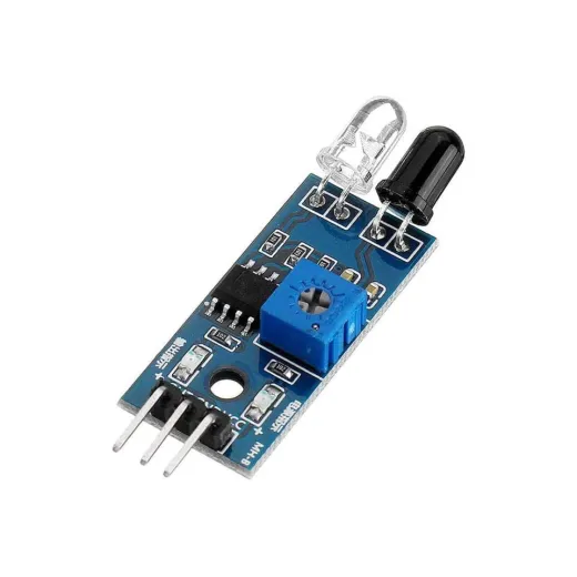
Circuit Diagram for IR Sensor
The circuit diagram for an infrared sensor represents a fundamental and widely used sensor module in electronics. Functioning akin to the visual senses of humans, this sensor aids in obstacle detection, finding widespread application in real-world scenarios. Its components include:
- LM358 IC
- Two pairs of IR transmitters and receivers
- Kilo-ohm range resistors
- Variable resistors
- Light Emitting Diode (LED)
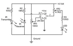
In this undertaking, the transmitter segment incorporates an IR sensor that continuously emits IR rays intended for reception by an IR receiver module. The IR receiver's output terminal undergoes variation based on its IR ray reception. Since this variation necessitates analysis, the output is directed to a comparator circuit. Here, an operational amplifier, specifically the LM339, serves as the comparator circuit.
When the IR receiver fails to detect a signal, the potential at the inverting input surpasses that at the non-inverting input of the LM339 comparator IC. Consequently, the comparator's output goes low, and the LED remains unilluminated. Conversely, when the IR receiver module detects a signal, the potential at the inverting input diminishes, causing the LM339 comparator's output to go high, thereby initiating LED illumination.
Resistors R1 (100Ω), R2 (10kΩ), and R3 (330Ω) regulate the flow of a minimum of 10 mA current through the IR LED, photodiode, and regular LEDs, respectively. Potentiometer VR2 (preset = 5kΩ) facilitates adjustment of the output terminals, while potentiometer VR1 (preset = 10kΩ) governs the circuit diagram's sensitivity.
IR Sensor Circuit with Transistors
Displayed below is the circuit diagram of an IR sensor employing transistors, specifically designed for obstacle detection utilizing an IR LED. This setup employs two transistors, namely NPN and PNP. The NPN transistor selected for this purpose is the BC547, while the BC557 is utilized for the PNP configuration. Notably, both transistors share identical pinouts.

In the depicted setup, one of the infrared LEDs remains in a permanently activated state, while the other is linked to the base terminal of the PNP transistor, functioning as the detector. Essential components for this IR sensor circuit encompass 100 ohms and 200 ohms resistors, BC547 and BC557 transistors, LED, and two IR LEDs. The procedural steps for constructing the IR sensor circuit are outlined below:
1. Assemble the components according to the provided circuit diagram, utilizing the specified components.
2. Connect one infrared LED to the base terminal of the BC547 transistor.
3. Attach another infrared LED to the same transistor's base terminal.
4. Wire the 100Ω resistor to the remaining pins of the infrared LEDs.
5. Link the base terminal of the PNP transistor to the collector terminal of the NPN transistor.
6. Establish connections for the LED and 220Ω resistor according to the circuit diagram.
7. Upon completion of the circuit connections, supply power to initiate testing.
Circuit Operation
Upon detection of infrared LED activation, the reflected light triggers a small current, energizing the IR LED detector. This action activates both the NPN and PNP transistors, resulting in LED illumination. This circuit finds application in various projects, such as automatically activating lamps when someone approaches the light source.
IR Burglar Alarm Circuit
The IR burglar alarm circuit is typically deployed at entry points such as doors to provide a warning sound, alerting individuals when someone passes through the IR beam. As IR rays are invisible to humans, this circuit serves as a discreet security mechanism.
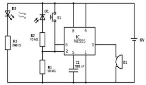
The essential components for this circuit comprise the NE555IC, along with resistors R1 and R2 (10kΩ and 560Ω respectively), IR photodiode (D1), IR LED (D2), capacitor C1 (100nF), push switch (S1), buzzer (B1), and a 6V DC power supply.
To assemble the circuit, position the infrared LED and sensors opposite each other on the door to ensure proper alignment of the IR beam. Under normal circumstances, the infrared beam consistently falls on the infrared diode, maintaining the output at pin 3 in a low state.
However, this beam is interrupted when a solid object crosses its path. Upon interruption, the circuit activates, causing the output to switch to an ON state. The alarm remains active until the interruption is rectified by closing the switch, meaning the alarm remains ON as long as the interruption persists. To prevent unauthorized deactivation of the alarm, the reset switch should be positioned remotely or out of sight from the infrared sensor.
In this configuration, a buzzer (B1) is connected to generate audible alerts, although it can be substituted with alternative bells or loud sirens based on specific requirements.
For further information on IR Sensor Module Interfacing with Microcontroller – Arduino, PIC, please refer to this link: [Insert Link Here]
Advantages
The benefits of IR sensors are as follows:
1. Low power consumption
2. Motion detection feasible in both light and dark conditions with comparable reliability
3. Non-contact detection eliminates the need for physical contact with objects
4. Directional rays prevent data leakage
5. Resistant to oxidation and corrosion
6. Strong immunity to noise
Disadvantages
However, IR sensors also have certain limitations:
1. Require a clear line of sight for operation
2. Limited detection range
3. Susceptible to interference from environmental factors like fog, rain, and dust
4. Lower data transmission rates compared to other technologies
Applications of IR Sensors
IR sensors find diverse applications across various fields. Some notable examples include:
1. Speed sensors for synchronizing multiple motors
2. Temperature sensors for industrial temperature control
3. PIR sensors for automatic door opening systems
4. Ultrasonic sensors for distance measurement
Additionally, IR sensors are integral to numerous sensor-based projects and electronic devices used for temperature measurement and monitoring.
Radiation Thermometers
IR sensors play a crucial role in radiation thermometers, enabling temperature measurement based on object material and temperature. These thermometers offer the following features:
1. Non-contact temperature measurement
2. Rapid response time
3. Simple pattern measurements
Flame Monitors
These devices detect emitted light from flames, monitoring their combustion. Flames emit light spanning from UV to IR regions. Commonly used detectors in flame monitors include PBS, PbSe, two-color detectors, and pyroelectric detectors.
Moisture Analyzers
Moisture analyzers utilize IR wavelengths absorbed by moisture. Objects are exposed to light at specific wavelengths (1.1 µm, 1.4 µm, 1.9 µm, and 2.7µm) and reference wavelengths. The analyzer detects light reflected from objects, correlating with moisture content. GaAs PIN photodiodes and PbS photoconductive detectors are common components in moisture analyzer circuits.
Gas Analyzers
IR sensors are essential in gas analyzers leveraging gas absorption characteristics in the IR region. Two measurement methods are employed: dispersive and nondispersive.
1. Dispersive Method: Emitted light is spectrally divided, and gas absorption characteristics are analyzed to determine gas composition and concentration.
2. Nondispersive Method (NDIR Technology): This widely used method utilizes gas absorption without spectral division. Discrete optical bandpass filters, akin to sunglasses, filter unwanted UV radiation. NDIR technology is employed in carbonated drinks analysis and automobile exhaust gas leakage detection.
IR Imaging Devices
IR imaging devices are prominent applications of IR waves, exploiting their invisible nature. These devices find extensive use in thermal imagers, night vision equipment, and similar applications.
For instance, various materials such as water, rocks, soil, vegetation, human tissue, and the atmosphere emit IR radiation. Thermal infrared detectors capture these emissions within the IR range, generating spatial temperature maps of objects or areas. Thermal imagers typically employ sensors like Sb (indium antimonite), Gd Hg (mercury-doped germanium), and Hg Cd Te (mercury-cadmium-telluride).
Electronic detectors are cooled to low temperatures using liquid helium or liquid nitrogen to ensure that recorded radiant energy originates from the terrain rather than the scanner's internal ambient temperature.
Key applications of infrared sensors span across diverse fields, including:
1. Meteorology
2. Climatology
3. Photobiomodulation
4. Water analysis
5. Gas detection
6. Anesthesiology testing
7. Petroleum exploration
8. Railway safety
In conclusion, infrared sensors are integral to many sensor-based electronic projects, offering enhanced understanding of their principles and applications. Should you have any queries or require further information, feel free to provide feedback in the comment section below. As for your question, yes, infrared thermometers can operate in complete darkness since they measure temperature based on emitted IR radiation rather than visible light.
Related Articles
Intelligent Sensors: Definition, Configurations, and Utilizations


