


What a PID Controller is Explained
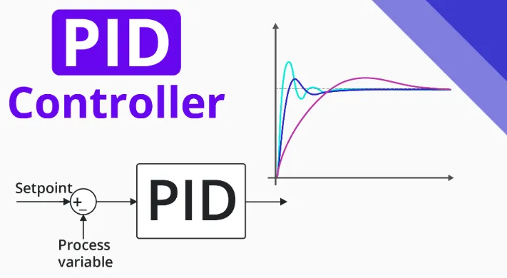
As implied by its title, this article aims to provide a concise overview of the structure and functionality of PID controllers. To start off, let's delve into what PID controllers entail. Widely employed across various industrial sectors for process control, PID controllers dominate approximately 95% of closed-loop operations within the realm of industrial automation. The acronym PID stands for Proportional-Integral-Derivative, signifying the amalgamation of these three controllers to generate a control signal. Functioning as a feedback controller, PID ensures the delivery of control output at predetermined levels. In the past, prior to the advent of microprocessors, PID control was executed using analog electronic components. However, in contemporary times, all PID controllers are processed through microprocessors. Additionally, programmable logic controllers often feature built-in PID controller instructions. Owing to their adaptability and dependability, PID controllers have long been the preferred choice for process control applications.
What is a PID Controller?
The acronym PID represents proportional integral derivative, which serves as a device employed for regulating various process variables such as pressure, flow, temperature, and speed within industrial settings. Within this controller framework, a feedback mechanism within the control loop is utilized to manage all the aforementioned process variables.
This form of control is applied to steer a system towards a predetermined target or level. It finds widespread application in temperature regulation across scientific processes, automation, and various chemical processes. Within this controller setup, closed-loop feedback is harnessed to ensure that the actual output of a system closely aligns with the target output or, ideally, remains fixed at a predetermined point whenever feasible. This article delves into the design of PID controllers, encompassing the utilization of control modes such as proportional (P), integral (I), and derivative (D).
History
The evolution of the PID controller dates back to 1911 when Elmer Sperry developed the first iteration. Subsequently, in 1933, the Taylor Instrumental Company (TIC) introduced a pneumatic controller that was fully adjustable. Control engineers, over time, addressed the steady-state error inherent in proportional controllers by iteratively adjusting the settings until the error reached zero. This adjustment method gave rise to the proportional-integral (PI) controller.
Further advancements occurred in 1940 with the development of the first pneumatic PID controller, incorporating derivative action to mitigate overshooting issues. Ziegler and Nichols revolutionized PID controller tuning in 1942 by introducing tuning rules that enabled engineers to determine and set optimal parameters.
By the mid-1950s, automatic PID controllers had gained widespread acceptance and were extensively utilized across various industries.
PID Controller Block Diagram
A closed-loop system, such as a PID controller, comprises a feedback control mechanism. This mechanism assesses the feedback variable against a reference point to generate an error signal, which in turn adjusts the system output. This iterative process persists until the error diminishes to zero or the feedback variable aligns with the reference point.
Compared to ON/OFF controllers, PID controllers yield superior outcomes. ON/OFF controllers operate based on two conditions: activation when the process value falls below a set threshold and deactivation when it exceeds the threshold. However, the output of ON/OFF controllers tends to fluctuate around the set point, resulting in instability. In contrast, PID controllers offer greater stability and accuracy, making them preferable for precise control applications.
Theory of of PID controller
Functioning of PID Controller
In contrast to a low-cost, basic ON-OFF controller, which offers only two control states—fully ON or fully OFF—PID controllers provide a more sophisticated solution. While ON-OFF controllers suffice for certain limited control applications, their inherent oscillatory nature constrains their utility, leading to their gradual replacement by PID controllers.
PID controllers operate within a closed-loop system to maintain output such that there is zero error between the process variable and the setpoint or desired output. These controllers integrate three fundamental control behaviors, elaborated as follows:
P-Controller
The proportional or P-controller generates an output that is directly proportional to the current error (e(t)). It compares the desired or setpoint value with the actual feedback process value. The resulting error is then multiplied by a proportional constant to yield the controller output. When the error value is zero, the output of this controller also becomes zero.
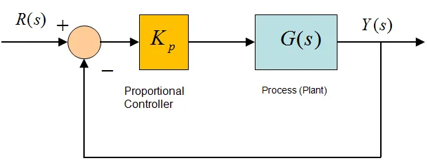
P-controller
This controller necessitates biasing or manual reset when utilized independently. This is due to its inability to reach a steady-state condition, resulting in consistent operation but persistent steady-state error. The responsiveness of the system is heightened with an increase in the proportional constant Kc.
I-Controller
Recognizing the inherent offset between the process variable and setpoint in the P-controller, the I-controller becomes essential to rectify the steady-state error. It accumulates the error over time until it diminishes to zero, thereby adjusting the final control device accordingly.
Integral control diminishes its output in response to negative errors, thereby regulating the system's response speed and influencing its stability. Reducing the integral gain, Ki, enhances the responsiveness of the system.
In the provided illustration, as the gain of the I-controller decreases, the steady-state error correspondingly diminishes. In most scenarios, the PI controller is preferred, especially in applications where high-speed responses are unnecessary.
When employing the PI controller, it's imperative to limit the output of the I-controller within a certain range to mitigate integral wind-up conditions, where the integral output continues to increase even at a state of zero error due to plant nonlinearities.
D-Controller
Unlike the I-controller, which lacks the capability to forecast future error behavior and typically reacts only after a setpoint change, the D-controller addresses this limitation by anticipating future error behavior. It calculates its output based on the rate of change of error over time, multiplied by the derivative constant. This anticipatory action kick-starts the output, thereby enhancing system response.
In the provided figure, the response of the D-controller exceeds that of the PI controller, leading to a decreased settling time of the output. By compensating for the phase lag induced by the I-controller, the D-controller improves system stability. Increasing the derivative gain further amplifies the system's response speed.
Thus, by amalgamating these three controllers, the desired system response can be achieved. Various manufacturers devise different PID algorithms to suit specific applications.
Types of PID Controller
PID controllers are typically categorized into three types: ON/OFF, proportional, and standard controllers. The selection of controller type depends on the characteristics of the control system and user preferences.
ON/OFF Control
An ON/OFF control method represents the simplest form of temperature control device. This controller's output toggles between ON and OFF states without an intermediate state. Once the temperature surpasses the setpoint, the controller activates the output. A particular variant of the ON/OFF controller, known as a limit controller, employs a latching relay to deactivate a process once a specified temperature threshold is reached.
Proportional Control
Designed to mitigate the cycling associated with ON/OFF control, the proportional PID controller modulates the power supplied to the heater as the temperature approaches the setpoint. It regulates the heater output to prevent it from exceeding the setpoint while ensuring a stable temperature. This proportioning action can be achieved by intermittently switching the output ON and OFF for brief periods, thereby adjusting the ratio of ON time to OFF time to control the temperature.
Standard Type PID Controller
The standard type PID controller integrates proportional, integral, and derivative controls to autonomously adjust the unit and compensate for changes within the system. These controls, integral and derivative, are expressed in units of time.
Alternatively referred to as RATE and RESET controllers, these PID controllers require individual adjustment or tuning for a specific system, often through trial and error. However, once tuned, they provide the most precise and stable control among the three types of controllers.
Real-Time PID Controllers
Today, a variety of PID controllers are readily available in the market to meet industrial control needs, such as pressure, temperature, level, and flow control. When employing PID control for these parameters, options include utilizing either a standalone PID controller or a PLC (Programmable Logic Controller).
Standalone controllers are employed in scenarios where one or two loops need monitoring and control or in situations where accessing larger systems is cumbersome. These devices offer various options for single and dual-loop control, providing multiple fixed-point configurations and autonomous alarms.
Prominent manufacturers of standalone controllers include Honeywell for PID controllers, Yokogawa for temperature controllers, OMEGA for autotune controllers, and Siemens and ABB for general-purpose controllers.
In many industrial control applications, PLCs are utilized in lieu of standalone PID controllers. The arrangement of PID blocks within PLCs or PACs (Programmable Automation Controllers) offers enhanced control options. PLC-based controllers are smarter and more powerful than standalone units, with each PLC incorporating PID blocks within its software programming.
Tuning Methods
Before the PID controller can effectively operate, it must undergo tuning to align with the dynamics of the process being controlled. Default values for the P, I, and D terms are often provided by designers; however, these values may not always yield the desired performance and can result in instability or sluggish control responses. Various tuning methods have been developed to adjust PID controllers, requiring careful consideration from operators to select the optimal values for proportional, integral, and derivative gains. Several of these methods are outlined below.
PID controllers find extensive use in industrial applications, necessitating an understanding of their settings to achieve the desired output. Tuning, in this context, refers to the process of eliciting an ideal response from the controller by establishing optimal proportional gains, integral, and derivative factors.
Tuning the PID controller is essential for obtaining the desired output. Various techniques are available to achieve this goal, including trial and error, Zeigler-Nichols, and process reaction curve methods. Among these, trial and error and Zeigler-Nichols methods are commonly employed.
Trial and Error Method: This method of PID controller tuning is straightforward. While the system or controller is in operation, adjustments are made to the controller settings. Initially, the integral (Ki) and derivative (Kd) terms are set to zero, and the proportional term (Kp) is gradually increased until the system exhibits oscillatory behavior. Once oscillations occur, the integral term is adjusted to eliminate the oscillations, followed by fine-tuning of the derivative term to achieve a rapid response.
Process Reaction Curve Technique: This technique involves open-loop tuning and is initiated by applying a step input to the system to elicit a response. Initially, a control output is manually applied to the system, and the resulting response curve is recorded. Subsequently, parameters such as slope, dead time, and rise time of the curve are calculated and utilized in the P, I, and D equations to determine the gain values of the PID terms.
Zeigler-Nichols Method: The Zeigler-Nichols method proposes closed-loop approaches for tuning the PID controller, which include the continuous cycling method and damped oscillation method. While the procedures for both methods are similar, they differ in oscillation behavior. Initially, the P-controller constant (Kp) is set to a specific value while Ki and Kd remain zero. The proportional gain is then gradually increased until the system exhibits sustained oscillations with a constant amplitude.
The gain at which the system produces constant oscillations is termed the ultimate gain (Ku), while the period of these oscillations is referred to as the ultimate period (Pc). Once these values are determined, the PID controller parameters (P, I, and D) can be configured using the Zeigler-Nichols table, depending on the type of controller utilized (P, PI, or PID).
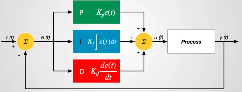
Structure of PID Controller
The PID controller comprises three components: proportional, integral, and derivative controls. The combined action of these controllers formulates a control strategy for process regulation. PID controllers manipulate process variables such as pressure, speed, temperature, and flow in various applications. In some instances, PID controllers are employed in cascade networks, where multiple PID controllers collaborate to achieve control objectives.
The structure of the PID controller, as depicted above, consists of a PID block transmitting its output to the process block. The process or plant incorporates final control devices like actuators and control valves to regulate industrial processes.
A feedback signal from the process plant is compared with a setpoint or reference signal (u(t)), resulting in an error signal (e(t)) fed into the PID algorithm. Through proportional, integral, and derivative control calculations within the algorithm, the controller generates a combined response or controlled output applied to plant control devices.
Not all control applications necessitate the use of all three control elements. Combinations such as PI and PD controls are frequently employed in practical applications.
Applications
The applications of PID controllers encompass a wide range of fields, including the following:
Temperature Control
One of the primary applications of PID controllers is temperature control, where the controller utilizes input from a temperature sensor to regulate a control element such as a fan or heater. Typically, the PID controller functions as just one component within a larger temperature control system, necessitating thorough consideration of the entire system for optimal controller selection.
Furnace Temperature Control
Furnaces are commonly employed for heating and maintaining large quantities of raw materials at high temperatures. Due to the substantial mass of the material involved, these systems exhibit significant inertia, resulting in relatively stable process variable (PV) signals. This stability allows the derivative term of the PID controller to effectively correct faults without causing abrupt changes to either the furnace control element (FCE) or the controlled output (CO).
Maximum Power Point Tracking (MPPT) Charge Controller
The V-I characteristic of a photovoltaic cell is highly dependent on temperature and irradiance levels. As weather conditions fluctuate, the current and operating voltage of the cell constantly change. Hence, it is crucial to track the maximum power point (MPP) of a photovoltaic system efficiently. PID controllers are utilized in MPPT charge controllers to track the MPP by providing fixed voltage and current setpoints. When weather conditions change, the controller adjusts the current and voltage to maintain stability.
Power Electronics Converter
PID controllers find widespread use in power electronics converters, where the output of the converter varies based on load changes. For instance, when an inverter is connected to a load, it supplies higher current as the load increases. The voltage and current parameters fluctuate accordingly, but the controller adjusts them based on demand. The PID controller generates pulse-width modulation (PWM) signals to activate the insulated-gate bipolar transistors (IGBTs) of the inverter, responding to load changes to maintain stability.
PID Controller Interfacing
The design and interfacing of PID controllers can be accomplished using microcontrollers such as Arduino. In laboratory settings, Arduino-based PID controllers are designed using Arduino UNO boards and electronic components, with software programming languages such as C or C++. This setup effectively regulates laboratory temperatures. Physical tuning of PID parameters for specific controllers is performed, enabling efficient temperature control with minimal deviation from the desired value.
Conclusion
This article provides an overview of PID controllers, covering their history, block diagram, structure, types, operation, tuning methods, interfacing, advantages, and applications. It aims to offer fundamental yet comprehensive insights into PID controllers. As a closing thought, the preferred tuning method for achieving optimal PID controller performance is the Zeigler-Nichols method, as it provides systematic guidelines for tuning PID parameters based on system response characteristics.


