


What Armature Is and How It works
The first armature was used by magnet keepers in the 19th century. The related equipment parts are described in both electrical and mechanical terms. While these two sets of terms are distinct, they are often used interchangeably, typically pairing one electrical term with one mechanical term. This can lead to confusion, especially when dealing with complex machines like brushless alternators. In most generators, the rotor part is the active field magnet, meaning it rotates, while the stator part is the inactive armature. Both generators and motors can be designed with either an inactive armature and an active (rotating) field, or an active armature and an inactive field. The shaft piece of a fixed magnet or electromagnet, as well as the moving iron piece of a solenoid, especially if the latter acts as a switch or relay, can also be referred to as armatures. This article provides an overview of the armature, its workings, and applications.
What is an Armature?
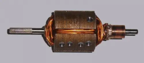
An armature is a power-generating component in an electric machine, and it can either be a rotating or stationary part within the machine. The interaction between the armature and the magnetic flux occurs in the air gap. The field element may consist of permanent magnets or electromagnets formed with a conducting coil, sometimes serving as another armature, known as a doubly-fed electric machine. The armature always functions as a conductor, oriented perpendicularly to both the field and the direction of motion, torque, or force. The armature diagram is shown below.
The primary function of an armature is multi-purpose. Its main role is to carry current across the field, thereby generating shaft torque in a rotary machine or force in a linear machine. Additionally, the armature produces an EMF (electromotive force), which arises due to the relative motion between the armature and the field. When the machine operates as a motor, the EMF opposes the armature current and converts electrical power into mechanical power in the form of torque, which is then transmitted through the shaft.
When the machine is used as a generator, the armature's electromotive force drives the armature current, and the shaft's motion is converted into electrical power. In this case, the generated power is drawn from the stator. A growler is typically used to test the armature for open circuits, grounds, and shorts.
Armature Components
An armature consists of several components, including the core, the winding, the commutator, and the shaft.
.webp)
Armature Core
The armature core is constructed from numerous thin metal plates called laminations. The laminations are typically around 0.5mm thick, depending on the frequency for which the armature is designed to operate. The metal plates are punched out in a circular form with a hole in the center, allowing the shaft to be pressed in, and with slots around the edge where the coils will eventually be placed. These metal plates are stacked together to form the core.
Using stacked metal plates rather than a solid piece of steel helps reduce energy losses in the form of heat within the core. These energy losses, known as iron losses, are caused by eddy currents. Eddy currents are small circulating magnetic fields that occur within the metal due to the rotating magnetic fields present when the unit is in operation. By using laminated plates, the eddy currents are confined to individual planes, significantly reducing these losses.
The Armature Winding
Before winding begins, the core slots are insulated to prevent the copper wire from contacting the laminated core. Coils are then placed into the armature slots and connected to the commutator in a rotating assembly. This process can vary depending on the armature's design.
Armatures can be classified into two types: lap wound armature and wave wound armature. In a lap wound armature, the end of one coil connects to a commutator segment and the beginning of the next coil. In a wave wound armature, the two ends of the coils connect to commutator segments separated by some distance among the poles.
This arrangement allows for the additive combination of voltages in the windings between the brushes, requiring only one pair of brushes. In a lap wound armature, the number of parallel paths equals the number of poles and brushes. Some armature designs feature two or more separate coils in the same slot, connected to adjacent commutator segments. This is done if the voltage required across the coil is considered to be high.
By distributing the voltage across three separate segments and coils in the same slot, the magnetic field strength in the slot increases, but it reduces arcing over the commutator and enhances the device's efficiency. In some armatures, the slots are skewed, achieved by slightly misaligning each lamination. This reduces cogging and provides a smoother transition from one pole to another.
The Armature Commutator
The commutator is mounted on the shaft and is held in place by a coarse knurl, similar to the core. It is made from copper bars, separated by an insulating material. Typically, this material is a thermoset plastic, though older armatures used sheet mica. The commutator must be precisely aligned with the core slots when installed on the shaft, as the wires from each coil emerge from the slots and connect to the commutator bars. To ensure efficient operation of the magnetic circuit, the armature coil must have an exact angular displacement relative to the commutator bar to which it is connected.
The Armature Shaft
The shaft of an armature is a sturdy rod mounted between two bearings that define the axis of the components placed on it. It must be thick enough to transmit the torque required by the engine and rigid enough to withstand any imbalanced forces. For minimal harmonic distortion, the length, speed, and bearing points are carefully chosen. An armature is composed of several major components: the core, the winding, the shaft, and the commutator.
Armature Function or Armature Working
The rotation of the armature is caused by the interaction of two magnetic fields. One magnetic field is generated by the field winding, while the other is produced by the armature when voltage is applied to the brushes, making contact with the commutator. When current flows through the armature winding, it generates a magnetic field. This field is misaligned with the field created by the field coil.
This misalignment creates an attractive force toward one pole and a repulsive force from the other. As the commutator is connected to the shaft, it rotates by the same amount, causing the poles to activate. The armature continues to follow the poles, resulting in rotation.
If voltage is not applied to the brushes, the field coil can still be excited, and the armature can be mechanically driven. The voltage applied is AC, causing it to flow toward and away from the pole. However, since the commutator is attached to the shaft and continuously switches polarity as it rotates, the actual output observed across the brushes is DC.
Armature Winding and Armature Reaction
The armature winding is the winding in which the voltage is induced. Similarly, the field winding is the winding that generates the main field flux when current flows through it. The armature winding involves basic components such as turns, coils, and windings.
Armature reaction refers to the effect of the armature flux on the main field flux. Typically, a DC motor has two windings: the armature winding and the field winding. When the field winding is energized, it produces a flux that interacts with the armature, resulting in an induced emf and a flow of current in the armature.
Applications of Armature
The applications of an armature include the following:
- The armature is used in electric machines for generating power.
- The armature can function as either a rotor or a stator.
- It is used to monitor current in DC motor applications.
Thus, this covers an overview of an armature, including what an armature is, its components, working principle, and applications. From the above information, we can conclude that an armature is a crucial component used in electric machines for generating power. It can be part of either the rotating or stationary part of the machine. Here is a question for you: how does an armature work?
Related Articles
Need Actuator Valves? What You Should Know!
Piezoelectric Actuator transducer : Principle & Its Applications
What Mechanical Actuator is and How it works


