


What Is a Current Divider? Simple Explanation
Introduction
A current divider is a concept element of the analysis of electrical and electronic circuits that describes the division of electric current as it passes through parallel circuits. In contrast with series circuits (where the same current is present in each component), in parallel circuits current is shared between two or more branches depending on their resistance to current or impedance. Knowing current dividers is also fundamental to the beginner since it is the basis of understanding real world circuits that are used in power delivery, signal processing, sensing and analog electronics.
What Is a Current Divider?
A current divider is an act or principle that is applied to decide the division of total current entering a parallel circuit between the parts. When a current source is connected to activate two or more parallel circuit components the current does not pass equally to the components; rather it is apportioned in inverse proportion to the resistance of a path. Simply put, a lower resistance in a circuit results in more current flowing through its branches and the higher the resistance the less the current flowing through the branch.
How Does a Current Divider Work?
Basic Working Principle
Divider functioning is grounded on the Ohm Law and Kirchhoff Current Law (KCL). According to the Current Law of Kirchhoff, the sum of current entering a junction has to be equal to the sum of current exiting the junction. In a parallel circuit, the voltage across the circuits of the circuit is the same and hence, the current in each branch is determined by its resistance only. Since current equals voltage divided by resistance, a branch with lower resistance draws more current under the same voltage conditions.
Current Divider Rule Explained
The current divider rule provides a quick mathematical way to calculate branch currents without solving the entire circuit step by step. Instead of calculating voltage first, the rule allows direct determination of how much current flows through each resistor based on resistance ratios. This rule is valid for linear, passive components such as resistors and impedances and assumes ideal sources unless otherwise stated.
Current Divider Formula
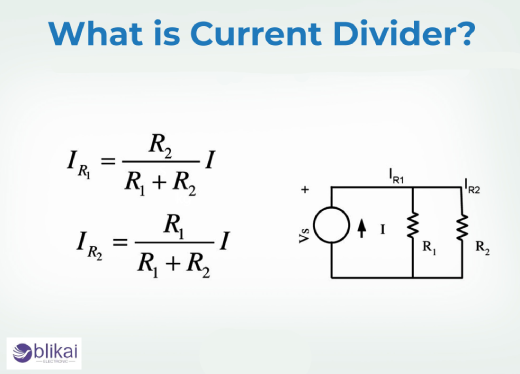
Two-Resistor Current Divider Equation
In a simple parallel circuit with two resistors, the formula of the current divider is the current flowing through one of the resistors is the total current multiplied with the resistance of the other branch divided by the addition of the two resistances. This negative relationship justifies why current follows the path of least resistance and makes calculations of current divider to be intuitive when the concept is learnt.
Current Divider Formula for Multiple Resistors
The same applies when more than two resistors are in parallel, where calculations are usually done using conductance or equivalent resistance. The currents in every branch are proportional to the reciprocal of the resistance of a branch divided by the total conductance of the circuit. This method is usually applied in more sophisticated networks like the biasing circuits and current sharing design.
Current Divider vs Voltage Divider
Key Differences Between Current and Voltage Dividers
The main difference between a current divider and a voltage divider lies in circuit configuration and behavior. A voltage divider operates in series circuits and divides voltage across components, while a current divider operates in parallel circuits and divides current among branches. In voltage dividers, current is constant across the entire circuit but in current dividers voltage is constant across each branch.
When to Use a Current Divider Instead of a Voltage Divider
When dealing with a parallel connection of components and current distribution is the primary issue, e.g. load sharing, current sensing, or protection circuits, a current divider is employed. These two concepts are easily mixed up, as beginners are used to, but the first thing that comes to mind about the components is that they are in series or in parallel and the rule of divider is immediately clear.
Current Divider Example Circuits
Simple Current Divider Example
Consider a parallel circuit with two resistors connected to a current source. The current divider rule can be used to divide the total current in the two branches without the calculation of the voltage across the network. This technique is particularly helpful in apt hand calculation and conceptual analysis when designing a circuit.
Current Divider with Unequal Resistances
In case the resistances are not equal, the division of current is even more intense. A branch with much lower resistance will carry a significantly larger portion of the total current. This behavior is exploited in practical designs such as shunt resistors, current mirrors, and sensing circuits where controlled current distribution is required.
Current Divider in Real Circuits
Current dividers are used in real electronic circuits in transistor bias networks, analog front-end designs, and power supply distribution, etc. Engineers use current division to control current flow through sensitive components and ensure stable operation across varying loads.
Current Divider in AC Circuits
Using Impedance Instead of Resistance
In alternating current (AC) circuits, current division depends on impedance rather than pure resistance. Impedance is a combination of resistance, capacitance and inductance, thus current division becomes frequency-dependent. Capacitors and inductors cause phase shifts, and this would alter the direction and strength of the current flowing.
AC Current Divider Formula
The AC version of the current divider rule replaces resistance with complex impedance. This allows engineers to analyze current distribution in filters, signal paths, and power electronics. As frequency changes, impedance changes, causing current to redistribute dynamically among parallel components.
Advantages of Current Dividers
Current dividers provide a fast and efficient way to analyze parallel circuits without extensive calculations. They simplify circuit analysis, improve design intuition, and are widely applicable in both DC and AC systems. For educational purposes, they help beginners quickly understand how current behaves in parallel networks.
Disadvantages of Current Dividers
The current divider rule assumes ideal components and linear behavior. In real circuits, component tolerances, temperature changes, and non-linear devices such as diodes and transistors can affect accuracy. This has led to the fact that current dividers are only applicable as an approximation or as a point of commencement to detailed analysis.
Common Mistakes When Using the Current Divider Rule
A well-known error is to use the current divider rule to series circuits, which is nonexistent there. The other common mistake is the assumption that current divides equally and does not take into account the values of resistance. Ignoring internal resistance of current sources or measurement devices can also lead to incorrect results, especially in precision applications.
Practical Applications of Current Dividers
Current dividers are widely used in current sensing, load balancing, analog signal conditioning, and power electronics. They help distribute current safely across parallel loads, protect sensitive components, and enable accurate current measurement using shunt resistors. In modern electronics, current division is essential for efficient energy management and reliable circuit operation.
Current Divider Summary
A current divider is a way that electric current is divided in a parallel circuit depending on the resistance or impedance. With the knowledge of the existing divider rule, the beginners acquire a potent instrument of analyzing and designing electronic circuits. This concept forms a bridge between basic circuit theory and real-world electronic applications.
FAQ
Why does current split unevenly in parallel circuits?
The current distribution is not uniform due to the difference in resistance of each branch and current is more likely to follow a path of lesser resistance.
Can current dividers be used in AC circuits?
Yes, when the resistance is substituted by impedance, current distribution during AC circuits is current-dependent, and the current dividers are current.
Where are current dividers used in real electronics?
They are applicable in current sensing, biasing networks, load sharing, and power distribution, and analog circuit design.
Some images are sourced online. Please contact us for removal if any copyright concerns arise.


