


Capacitive Voltage Divider : Prinple & Its Applications
In electronics, a voltage divider, also known as a potential divider, serves as a passive linear circuit designed to yield an output voltage that constitutes a fraction of its input voltage. Voltage division arises from the allocation of the input voltage across the components of the voltage divider. Typically, in a voltage divider configuration, two resistors are arranged in series. The input voltage is applied across these resistors, while the output voltage is extracted from the junction between them. Various types of voltage divider circuits exist, each tailored to specific applications. These include resistive, inductive, low-pass RC filter, and capacitive voltage divider circuits. This article offers a concise overview of one such type, namely the Capacitive Voltage Divider, elucidating its operation and applications.
What is a Capacitive Voltage Divider?
A capacitive voltage divider constitutes a type of voltage divider circuit employing capacitors as the voltage-dividing elements. Analogous to resistors, capacitors can partition voltage within a circuit, enabling the division of voltage into discrete portions based on the capacitor's value. In a capacitive voltage divider circuit, capacitors are arranged in series, akin to a voltage divider circuit utilizing resistors, to establish a voltage divider network in conjunction with a voltage source.
How does a Capacitive Voltage Divider Operate?
Capacitive voltage dividers present a more intricate operation compared to resistive networks due to the reactive nature of capacitors. Consequently, the resistance provided by capacitors in the circuit is primarily contingent on the frequency of the input signal. The resistance of a capacitor, denoted as Xc, is measured in ohms and is inversely proportional to the capacitance value.
Hence, \( X_C \propto \frac{1}{C} \)
When the frequency of the source current is low, the charging time of the capacitor increases. Conversely, if the frequency of the current source is high, the charging time of the capacitor decreases. Ultimately, when denoting frequency as 'F', capacitive reactance as 'Xc', and capacitance value as 'C', the equation can be expressed as:
XC ∝ 1/C
The Equation for Capacitive Reactance \( X_C = \frac{1}{2\pi fC} \)
Here,
- \( X_C \) represents the reactance of the capacitor in ohms (Ω).
- \( f \) denotes the frequency in Hertz (Hz).
- \( C \) signifies the capacitance of the capacitor in farads (F).
- \( \pi \) is the mathematical constant (3.1416).
Capacitive Voltage Divider Circuit
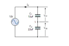
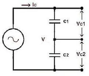
Displayed below is the capacitive voltage divider circuit utilized to determine the voltage divider principle of capacitors. In this configuration, two capacitors are serially connected with voltage sources denoted as \( V_s \). Subsequently, the voltage source divides into two, where one supply traverses the C1 capacitor and the other passes through the C2 capacitor. Additionally, VC1 in the circuit represents the voltage across the C1 capacitor, while VC2 denotes the voltage across the C2 capacitor.
Therefore, the total capacitance can be expressed as:
\[ \frac{1}{C_{eq}} = \frac{1}{C_1} + \frac{1}{C_2} \]
\[ C_{eq} = \frac{C_1C_2}{C_1 + C_2} \]
The charge provided by the source \( Q = C_{eq} \times V_s \), which can be simplified to:
\[ Q = \left(\frac{C_1C_2}{C_1 + C_2}\right) \times V_s \]
The voltage across capacitor \( C_1 \) is denoted as \( V_{C1} \):
\[ V_{C1} = \frac{Q_1}{C_1} \]
\[ V_{C1} = \frac{\left(\frac{C_1C_2}{C_1 + C_2}\right) \times V_s}{C_1} \]
\[ V_{C1} = \frac{V_s}{C_1 + C_2} \times C_2 \]
The voltage across capacitor \( C_2 \) is denoted as \( V_{C2} \):
\[ V_{C2} = \frac{Q_2}{C_2} \]
\[ V_{C2} = \frac{\left(\frac{C_1C_2}{C_1 + C_2}\right) \times V_s}{C_2} \]
\[ V_{C2} = \frac{V_s}{C_1 + C_2} \times C_1 \]
Thus, the individual voltage across a capacitor is a fraction of the opposite capacitance multiplied by the total capacitance and voltage.
Example Problems
A capacitive voltage divider works with both AC and DC, with the formulas for both being nearly identical. Here are example problems for both AC and DC capacitive voltage divider circuits.
Capacitive AC Voltage Divider Circuit Example
The diagram below illustrates an example capacitive AC voltage divider circuit. The voltage source is 120V with a frequency of 1500 Hz. Two capacitors in the circuit are connected in series: \( C_1 = 3 \mu F \) with a capacitance \( X_C \) of 30 ohms, and \( C_2 = 1 \mu F \) with a capacitance \( X_C \) of 60 ohms.
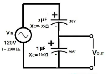
The voltage drop across each capacitor, denoted as \( V_{C1} \) and \( V_{C2} \), is calculated as follows:
The reactance of the 3μF capacitor is given by:
\[ X_{C1} = \frac{1}{2πfC_1} = \frac{1}{2 \times 3.142 \times 1500 \times 3 \times 10^{-6}} = \frac{10^6}{28278} \approx 35 \, \Omega \]
The reactance of the 1μF capacitor is given by:
\[ X_{C2} = \frac{1}{2πfC_2} = \frac{1}{2 \times 3.142 \times 1500 \times 1 \times 10^{-6}} = \frac{10^6}{9426} \approx 106 \, \Omega \]
The total capacitive reactance of the circuit is \( X_C = X_{C1} + X_{C2} = 35 \, \Omega + 106 \, \Omega = 141 \, \Omega \)
The current flowing through the circuit is:
\[ I = \frac{V}{X_C} = \frac{120 \, V}{141 \, \Omega} \approx 0.85 \, mA \]
The voltage drop across each capacitor is:
\[ V_{C1} = I \times X_{C1} = 0.85 \, mA \times 35 \, \Omega = 29.75 \, V \]
\[ V_{C2} = I \times X_{C2} = 0.85 \, mA \times 106 \, \Omega = 90.01 \, V \]
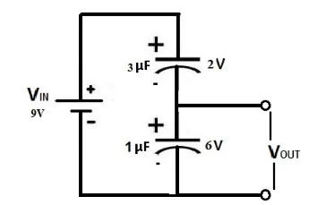
For a capacitive DC voltage divider circuit example, the circuit diagram is depicted below. The voltage source is 9V, and two capacitors are connected in series, where \( V_{C1} \) is 3μF and \( V_{C2} \) is 1μF. In this scenario, the DC voltage divider allocates the voltage according to the formula \( V = \frac{Q}{C} \). If the frequency of the circuit is 12 kHz or 12000 Hz, the output voltage of DC can be determined.
For the 3μF capacitor, the reactance \( X_{C1} \) can be calculated using the formula \( X_{C1} = \frac{1}{2\pi fC1} = \frac{1}{2 \times 3.142 \times 12000 \times 3 \times 10^{-6}} = \frac{10^6}{226224} = 4.420Ω \).
Similarly, for the 1μF capacitor, the reactance \( X_{C2} \) is \( X_{C2} = \frac{1}{2\pi fC2} = \frac{1}{2 \times 3.142 \times 12000 \times 1 \times 10^{-6}} = \frac{10^6}{75408} = 13.26Ω \).
The total capacitive reactance of the circuit \( X_C \) can be found by adding \( X_{C1} \) and \( X_{C2} \), which equals \( 4.420Ω + 13.26Ω = 17.68 Ohms \).
The current \( I \) flowing through the circuit is \( I = \frac{V}{X_C} = \frac{9V}{17.68Ω} = 0.50mA \).
The voltage drop across each capacitor is then calculated:
\( V_{C1} = I \times X_{C1} = 0.50mA \times 4.420Ω = 2.21V \)
\( V_{C2} = I \times X_{C2} = 0.50mA \times 13.26Ω = 6.63V \)
Note: Alternatively, the capacitive voltage divider formula \( C_T = \frac{C1 \times C2}{C1 + C2} \) can be used to find the total capacitance, and then \( X_{C_T} = \frac{1}{2\pi fC_T} \).
Advantages and Disadvantages
Capacitive voltage dividers offer several advantages:
Cost-effective.
Lower heat dissipation.
Suitable for both AC and DC applications.
Low installation expenses.
Frequency-sensitive.
Capacitive voltage dividers provide numerous benefits such as rapid pulse signal measurement owing to their broad bandwidth, swift response, stability, and high voltage division ratio.
However, there are some drawbacks to consider:
Relatively bulky.
Potential efficiency reduction due to overheating.
Limited applicability to AC-only scenarios for certain models.
Capacitive voltage dividers find various applications:
They are employed to step down high voltages for measurement purposes.
Ideal for capturing fast-rising voltages and pulses.
Utilized in microcontrollers to gauge sensor resistance.
Serve as logic level shifters for interfacing different voltage levels.
Find use in diverse electronic applications, ranging from Colpitts Oscillator circuits to capacitive touch-sensitive screens.
Widely utilized in electron beam accelerators to assess high-voltage output signals within nanosecond timeframes.
Simple capacitive voltage dividers are instrumental in measuring high-voltage signals ranging from nanoseconds to microseconds.
In summary, capacitive voltage dividers effectively manage potential differences while preserving voltage ratios. Now, can you explain what a resistive voltage divider is?
Related Articles
Does a Resistor Reduce Voltage
How Does a Voltage Regulator Work? [Completely Explained]
Operation & Fault Handling of High Voltage Switchgear Explained
Comparison: LM2576 vs. LM2596 Voltage Regulators
Voltage Amplifier vs Power Amplifier: What’s the Differences?


