


NE555 Calculator: Easy 555 Timer Circuit Design & Tools
Introduction to the NE555 Timer
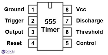
The NE555 timer is a popular electronic component, and IC is favored for its reliability and versatility. This chip was available in the 1970s but has now become a standard in both amateur and professional uses. It could produce correct time delays or square wave oscillation and is commonly used in sound generators, LED flashers and timers. It is possible to set the NE555 into three configurations: one-shot pulse (monostable), non-stop oscillation (astable) and flip-flop (bistable). These modes enable it to perform a wide variety of timekeeping and controlling purposes.
What Is an NE555 Calculator?
A NE555 calculator is an electronic aid in solving the engineer and hobbyist problem of calculating important timing parameters of their 555 timer circuits in a quick and easier manner. Instead of entering complicated formulas to calculate a parameter, the user only enters values of the components like resistors (R1 and R2) and a capacitor (C) and the calculator tells the user values of frequency, period, duty cycle, and pulse width. This also saves time, and the likelihood of committing an error will be eliminated, particularly during the prototyping stage. These calculators are found online, and they are also embedded in circuit design platforms so that you can easily go through numerous design iterations.
Common NE555 Timer Circuit Configurations
Astable Mode: In an astable mode, the NE555 timer is used as an oscillator that keeps switching between high and low states on the output terminals without using an external trigger. This is commonly adopted in applications such as LED blinkers, tone generators, and clock pulses in digital circuitry, among others. The time is fixed by the values of two resistors and a capacitor, and well-known formulas fix both the frequency and duty cycle.
Monostable Mode: Monostable mode generates a fixed pulse length; we can see that in monostable mode, the NE 555 outputs a single pulse of a specific duration upon the triggering of an external signal. One capacitor and one resistor fix the pulse length. The model is best suited to make timers, delay circuits and implement debounce actions in switch inputs. After a trigger, the output rises to a high state according to the computed time duration and later back to a low until re-triggered.
Bistable Mode: In the bistable mode, the NE555 behaves simply as a flip-flop or a latch. It has two external inputs to ON and OFF the output states. It is ideal in things like toggle switches, memory circuits and trivial state machines whose output state must remain constant until forcefully altered by some external signal.
How to Use a NE555 Calculator
Operating an NE555 calculator is really easy and a potent tool for circuit designing. First, you must choose the desired operating mode between astable and monostable. Please enter the value of R1, R2 and C into their independent fields next. The calculator will thereafter reveal output features like frequencies (Hz), HIGH of time (TH), LOW of times (TL), overall period (T), and proportion of duty cycle ( % ). As an example, consider a circuit with R1 = 1k, R2 = 2k and C = 1 microfarad astable mode. Then, the calculator will produce a frequency of about 333 Hz and a duty cycle of about 66 percent. Designers have the opportunity to adjust values to have the right output to suit particular cases in use.
Practical Applications of NE555 Timer Circuits
NE555 timer is incredibly versatile and is very useful even in the simplest and most complicated electric devices. It is used in LED flasher circuits to give regular on/off time of flashing lights. It modulates the motor speed in the PWM motor controller settings by changing the duty cycle. In good projects, it is a tone generator, which gives audio signals. Security and lighting systems have delay circuits that are automatic through the use of NE555 timers. The NE555-based projects lend themselves to hands-on learning of some of the fundamental concepts of timing and logic that are also relevant to electronics design and are, therefore, found in many DIY electronics kits.
Tips for Accurate NE555 Timer Circuit Design
Valid NE555 timer systems require the proper choice of parts and appropriate practices. To reduce variation, use resistors of 16 tolerance and high-quality (good) electrolytic or film capacitors. Wires having short and compact spots can minimize parasitic inductance and crosstalk, particularly on breadboards. Increasing stability by adding a 0.1uF ceramic capacitor close to the power pins of the IC will reduce voltage spikes. This will also improve overall stability. It is important to test the circuit in software to model the timing and functionality before settling your design.
Troubleshooting NE555 Timer Circuits
NE555 problems are common but are often related to wrong component values, an unfiltered power supply, or badly arranged wiring. In case the output is stuck at either high or low voltage, resistor and capacitor values should be checked again, and connections should be verified. In monostable mode, care must be taken to feed a clean, sharp signal to the trigger pin; any noise or bouncing may result in erratic results. When the oscillation does not occur in astable mode, check that the timing components are fixed firmly in position and the correct way up. Measure voltages using a multimeter and fool around with signal waveforms on an oscilloscope, should you have one.
NE555 Alternatives and IC Comparisons
While the NE555 is robust and widely available, other ICs offer different performance characteristics that may suit specific needs better:
|
IC |
Supply Voltage Range |
Output Drive |
Power Consumption |
|
NE555 |
4.5V - 15V |
Moderate |
Moderate |
|
LM555 |
4.5V - 16V |
High current (up to 200mA) |
Moderate |
|
TLC555 |
2V - 15V |
Lower current |
Very Low (CMOS design) |
TLC555 A variant of CMOS is useful with battery operation because it is a lighter-use design, whereas LM555 is suited to larger-output demands.
Conclusion
Calculators NE555 contribute to the simplification of work when it comes to designing timing circuits to a great extent, and this is the reason why every engineer and hobbyist should have one. These calculators can get rid of guesswork and give instant component selection and circuit behavior feedback. The NE555 is hands down among the most useful ICs in the world of electronics; with a substantial backing and simulation environment along with no limits on usage, the NE555 is here to stay. The use of these tools improves the learning process speeds up the development, and contributes to more reliable and efficient designs.
FAQs
Q1: Can I use an NE555 timer for PWM control?
Yes, by configuring the NE555 in astable mode and adjusting R1 and R2, you can achieve variable duty cycles suitable for PWM applications.
Q2: What’s the difference between LM555 and NE555?
LM555 can withstand larger output currents and larger ranges of voltages, whereas NE555 is the standard variant that is applied to general-purpose usage.
Q3: Do NE555 calculators work for CMOS versions like TLC555?
Yes, but we should make sure that the calculator is prepared to take into account the disparities of internal architecture and threshold voltages that come with the CMOS designs.
Q4: Why is my NE555 not oscillating in astable mode?
Ensure that R1, R2 and C have been properly connected and within the correct value range. One should also ensure that the power supply is steady and well-grounded.


