


Low Pass Filter Circuit: Design, Components & Applications
What Is a Low Pass Filter Circuit?
A low-pass filter circuit is an electronic circuit that is designed to pass through the signals whose frequencies fall below a preset cutoff frequency and attenuate higher-frequency signals. It is among the most essential signal conditioning systems in analog electronics, digital and power applications.
How Does a Low Pass Filter Work?
Basic Working Principle
The frequency-dependent impedance is the working principle of a low-pass filter circuit. The circuit offers minimal resistance to the signal at low frequencies and hence can transmit the signal with little attenuation. At and beyond the cutoff frequency, the signal is blocked or diverted by reactive components more and more, e.g., capacitors, inductors, and the strength of the output signal grows smaller. This selective behavior enables the circuit to suppress unwanted high-frequency noise while preserving the desired low-frequency content.
Frequency Response and Roll-Off
The frequency response of a low-pass filter is the manner in which too much or too little signal is produced with a change in frequency. At frequencies below the cutoff frequency, the signal works in the passband and has a comparatively constant gain. Beyond the cutoff frequency, the signal goes into a stopband where the signal attenuation grows at a rate commonly called roll-off. A first-order low-pass filter typically provides a roll-off of −20 dB per decade, while higher-order filters achieve steeper attenuation slopes for improved noise rejection.
Types of Low-Pass Filter Circuits
Passive Low Pass Filters
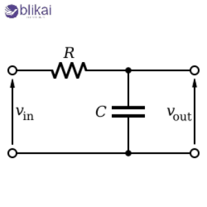
Passive low-pass filters are designed to imply no active amplification, but only resistors, capacitors, and inductors. The simplest passive type of design is the RC low-pass design, in which a simple frequency-selective network is composed of a resistor and a capacitor. Inductors are used in place of capacitors in RL low pass filters, and are normally used in power electronics and high-current applications, which already use inductors.
Active Low Pass Filters
Active low-pass filters use operational amplifiers in addition to resistors and capacitors to give filtering and signal amplification. These circuits offer improved control over gain, impedance matching, and frequency response compared to passive designs. Active filters are widely used in audio systems, instrumentation, and analog signal processing due to their stability and predictable performance.
Digital Low Pass Filters
Digital low-pass filters are frequency filters that are mathematically computed using microcontrollers, DSPs, or software. Common implementations include FIR (Finite Impulse Response) and IIR (Infinite Impulse Response) filters. Digital filters are more flexible and more precise; however, they need to be sampled and need processing power as well as appropriate anti-aliasing at the analog input stage.
Low Pass Filter Circuit Design
Cutoff Frequency Formula
The equation f(c) = 1/ (2 pRC) is used to determine the cutoff frequency of a simple RC low-pass filter. This frequency is the point where the amplitude of the output signal decreases to nearly 70.7 percent of the input value. To be sure that the filter fulfills the requirements of the system without tampering with the required signal, it is necessary to compute the cutoff frequency correctly.
Selecting Component Values
The trade-offs among frequency, component availability, power consumption and noise performance are that the correct choice of resistor and capacitor values depends on the trade-off among these parameters. The high values of resistance decrease the current drawn, but make the circuit more prone to noise; the larger values of capacitance can create size and cost limitations. Designers usually use standard values of their components, and performance is refined by testing or simulation.
Order of the Filter
The number of reactive elements in the circuit is the order of a low-pass filter. The first-order filters are inexpensive and easy to work with, yet they can only attenuate high-frequency signals to a small extent. Second-order and higher-order filters offer steeper roll-off and better noise suppression but require additional components and careful stability considerations, especially in active designs.
Key Components Used in Low Pass Filter Circuits
Resistors
Resistors characterise the time constant and cutoff frequency of low-pass filter circuits. Filter accuracy and long-term stability are directly proportional to their tolerance, temperature coefficient and power rating. Precision resistors are desired for uses that demand a constant frequency response.
Capacitors
The most common frequency-selective components of a low-pass filter are the capacitors. High-frequency applications: Ceramic and film capacitors are preferred in high and low-frequency circuits, respectively. Electrolytic capacitors find application in the low frequency filtering with high values of capacitance.
Inductors
In RL and LC low-pass filters, inductors are frequently employed, particularly in power supply and RF. Performance is affected by their inductance value, current rating and core material. During design, saturation and parasitic resistance should be mentioned.
Operational Amplifiers
The operation amplifier in active low-pass filters is critical in the determination of the gain and bandwidth. A good op-amp should be capable of processing the wanted signal frequencies with a good gain-bandwidth product and slew rate without distortion or phase error.
Low Pass Filter Circuit Diagrams and Examples
Resistive and inductive low-pass filter. A simple RC low-pass filter is a resistor in series with the input signal and a capacitor between the output and the ground. In this configuration, low-frequency signals appear at the output with minimal loss, while high-frequency components are shunted to ground through the capacitor. Examples of active low-pass filters include a general improvement of the op-amp-based topology of the Sallen-Key or multiple feedback configuration.
Applications of Low-Pass Filter Circuits
Audio Signal Processing
Low-pass filters find application in audio systems to filter high-frequency noise, bandwidth and sound output. They are needed in anti-aliasing, crossover networks, and tone controls in digital audio conversion.
Power Supply Filtering
Power supplies commonly use low-pass filters to minimize ripple, switching noise and electromagnetic interference. LC and RC filters are used to smooth the DC output voltages to enhance the reliability and performance of the system.
Sensor Signal Conditioning
The sensors can give noisy signals, which they must filter before converting to analog-to-digital. Low-pass filters also eliminate the undesired high-frequency noise, enabling physical parameters that change slowly, like temperature, pressure, and current, to be measured correctly.
Communication Systems
In communication circuits, low-pass filters control bandwidth, suppress harmonics, and act as anti-aliasing filters. They ensure signal integrity and compliance with spectral requirements in wired and wireless systems.
Advantages of Low Pass Filters
Low-pass filters are inexpensive and easy to design, and very multi-purpose. They are very useful in eliminating high-frequency noise and interference, and still retain the information that is useful. Their extensive implementations allow them to be applied to analog and digital systems.
Disadvantages of Low Pass Filters
Although low-pass filters have advantages, they introduce phase shift and signal delay, particularly at the cutoff frequency. Low-order filters may not provide sufficient attenuation for demanding applications, while higher-order designs increase complexity and sensitivity to component tolerances.
Common Low Pass Filter Design Mistakes
A permanent error is to choose the wrong cutoff frequency, which cancels the signal of interest. Ignoring component tolerances can lead to frequency drift and inconsistent performance. In active filters, insufficient op-amp bandwidth or poor layout practices may cause instability or noise amplification.
Low Pass Filter vs High Pass Filter
Low pass filters enable low frequency signals to pass through and high frequency attenuate the other way around, high pass filters. Noise reduction and smoothing are normally applied through low-pass filters, and DC blocking and edge detection through high-pass filters. The choice of filter type to use should be based on system needs and signal nature.
FAQs
Can a low-pass filter pass DC signals?
Yes, the majority of low-pass filter circuit designs permit DC and very low frequency signals to pass through with little to no attenuation, which makes them applicable in the process of smoothing and averaging.
What is the difference between passive and active low-pass filters?
Passive filters do not provide gain and rely solely on passive components, while active filters use operational amplifiers to offer amplification, buffering, and improved control over frequency response.
Conclusion
Low-pass filter circuits are crucial building blocks in contemporary electronic design, which offer good control of signal bandwidth and suppression of noise. Engineers can successfully employ low-pass filters in numerous applications by learning about their working principle, choice of components, design constraints, and so on. Regardless of whether one applies low-pass filters to simple RC networks or more complicated active setups, they continue to be a foundation block of signal processing and electronic systems design.
Some images are sourced online. Please contact us for removal if any copyright concerns arise.


