


What Passive Band Pass Filter is and How It works
Filter circuits eliminate certain frequencies within electronic systems. They utilize resistors and capacitors as their fundamental components. In a power supply block diagram, this filter circuit is necessary after the rectifier circuit because it converts pulsating AC to DC, providing a unidirectional current. The filter circuit removes the AC component from the rectified output and allows the DC component to reach the load. Among the different types of filters, the band pass filter (BPF) is one example. This filter permits frequencies within a specific range and attenuates those outside that range. There are various types of filters, with the passive BPF being one. This article provides an overview of a passive band pass filter, its operation, and its applications.
What is a Passive Band Pass Filter?
A passive band pass filter combines both low pass and high pass filters. It allows a specific band of frequencies while blocking all others. This electrical circuit uses only passive elements such as resistors, capacitors, and inductors. The filter is formed by cascading a low pass filter (LPF) and a high pass filter (HPF). Passive band pass filters are mainly used in audio amplifiers, where a certain frequency range is needed that does not start from 0 Hz and is not a high frequency, but falls within a particular band, whether wide or narrow.
Passive Band Pass Filter Circuit Diagram
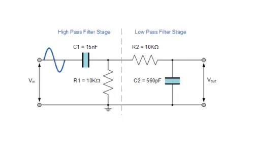
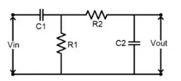
The passive band pass filter uses only passive components like resistors, inductors, and capacitors. Unlike active band pass filters, it does not use an operational amplifier for amplification. The circuit diagram of a passive band pass filter includes both high pass and low pass filter circuits. The first part of the circuit is for the passive HPF, while the second part is for the passive LPF.
Passive Band Pass Filter Design
Designing a passive band pass filter can be done easily using resistors and capacitors. This circuit does not require power and is not used for active amplification. While these types of filters can be used alongside an active circuit for amplification, they do not provide amplification on their own. They are designed by combining a high pass filter (HPF) and a low pass filter (LPF).
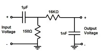
To create this circuit, the necessary components include capacitors (1nF and 1μF) and resistors (150Ω and 16KΩ). Only resistors and capacitors are needed to build this filter. For the chosen resistor and capacitor values, the pass band ranges from 1KHz to 10KHz. To modify these frequencies, the values of the resistors and capacitors need to be changed.
Passive Band Pass Filter
This circuit has two parts: a high pass filter and a low pass filter. The first part consists of R1 and C1, forming the high pass filter (HPF). This filter allows all frequencies above its designed cutoff point, which in this circuit is 1KHz. The lower cutoff frequency can be calculated using the formula:
The lower cut-off frequency = 1/2πR1C1.
Given the values R1 = 150Ω and C1 = 1μF, substituting these into the equation gives:
The lower cut-off frequency = 1/2π(150Ω)*(1μF) => 1061 Hz => 1KHz.
Therefore, the HPF allows frequencies above 1KHz and blocks or greatly attenuates frequencies below 1KHz.
Similarly, the second part of this circuit is composed of resistor R2 and capacitor C2, forming the low pass filter (LPF). This filter blocks all frequencies above the cutoff point.
In this circuit, the desired higher cutoff frequency is 10KHz, allowing frequencies below 10KHz to pass and blocking frequencies above 10KHz. The formula to calculate the higher cutoff frequency is the same as for the lower cutoff frequency:
frequency => 1/2π R2C2.
Given the values for the resistor and capacitor, R1 = 150Ω and C1 = 1μF, substituting these values into the equation, we get:
The lower cut-off frequency = 1/2π(150Ω)*(1μF) => 1061 Hz => 1KHz.
This filter allows all frequencies above 1KHz and blocks or greatly attenuates all frequencies below 1KHz.
Similarly, the second part of this circuit is composed of resistor R2 and capacitor C2 to form the low pass filter (LPF). This filter blocks all frequencies above the cutoff point.
For this filter circuit, the higher cutoff frequency is set to 10KHz. Therefore, this circuit allows all frequencies below 10KHz to pass and blocks all frequencies above 10KHz. The formula to calculate the higher cutoff frequency is the same as for the lower cutoff frequency.frequency => 1/2π R2C2.
Given the values for resistor R2 and capacitor C2, R2 = 16KΩ and C2 = 1nF, substituting these values into the equation, we get:
Higher cutoff frequency = 1/2π(16KΩ)*(1nF)= 9952Hz => 10KHz.
Thus, the HPF allows all frequencies above the lower cutoff point, while the LPF allows all frequencies below the higher cutoff frequency. This creates a band-pass filter with a passband between the lower and higher cutoff frequencies.
To avoid the loading effect on the LPF from the HPF, it is recommended that the value of resistor R2 should be at least 10 times greater than or less than the value of resistor R1. In this circuit, we make the value of resistor R2 100 times higher.
Working of Passive Band Pass Filter
This circuit works by allowing full-strength signals in between the low pass filter & the high pass filter frequencies. If the low-pass filter (LPF) is designed for 2KHz frequency whereas the high-pass filter (HPF) is designed for 200Hz frequency, then this circuit generates output signals between 200Hz & 2KHz with near full strength or complete strength.
When the generated signals are outside of this range frequencies will be attenuated greatly, thus their amplitudes are very low as compared to the amplitude of the signal within the pass band. The pass band refers to the signals in between the high pass and low passes filters which are passed throughout full strength.
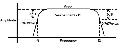
Here, the pass band is 200Hz to 2 KHz then the low cutoff frequency is 200Hz & the high cutoff frequency is 2 KHz. In the pass band, these two frequencies are the two points within the passband where there is a 3dB drop within amplitude. So this drop is equivalent to 0.707VPEAK.
In the following bandpass graph, there is peak amplitude (VPEAK). Here the amplitude will drop whenever you get these two frequencies. Once it achieves 0.707VPEAK, then this is the 3dB cutoff point that signifies half the maximum power. After the 3dB cutoff points, there is a steep drop in amplitude, thus frequencies outside of the cutoff frequencies are highly attenuated.
Passive Band Pass Filter
Here we have two main frequencies: the lower cutoff frequency at 1KHz and the higher cutoff frequency at 10KHz. The center frequency is the frequency between the higher and lower cutoff frequencies, calculated using the formula √(f1)(f2) => √ (1061)(9952) => 3249 Hz.
The output signal around this center frequency has full strength and reaches its highest peak value. As the frequency moves closer to the cutoff points, the amplitude attenuates or reduces. At the cutoff frequencies, the amplitude is 0.707VPEAK. For example, if VPEAK measures 10 volts from peak to peak at the cutoff frequencies, then the amplitude is approximately 7 volts, calculated as 10V * 0.707V => 7V.
Gain of Passive Band Pass Filter
The gain of the passive band pass filter is always less than the input signal, meaning the output gain is below unity. At the center frequency, the output signal is in phase. However, the output signal below the center frequency leads the phase with a +90° shift, while the output signal above the center frequency lags in phase by -90°. Providing electrical isolation between the two filters can enhance filter performance.
Applications of Passive Band Pass Filter
Passive band pass filters find application in various scenarios:
- - They are used to isolate or filter specific frequencies within a defined band or range.
- - These filters are employed in audio amplifier circuits and applications such as pre-amplifier tone controls and loudspeaker crossover filters.
- - They are integral to transmitter and receiver circuits in wireless communication mediums.
In summary, a passive band pass filter combines high pass (HPF) and low pass (LPF) filters to selectively allow a range of frequencies. This filter can accommodate both wide and narrow frequency ranges, with the cutoff frequencies determined by its design.
Here's a question for you: What is BPF?
Related Articles
FIR Filters:Overview,Structure and Signal Processing
What is Band Stop Filter: Design, Features and Applications
Exploring Band Reject Filters: Theory and Applications
Electromagnetic Interference Filter: Types, Advantages & Applications


