


Understanding Coupled Inductors: Operations and Practical Applications
An inductor is a fundamental electrical component designed with two terminals that store energy within a magnetic field when an electric current passes through it. Sometimes referred to as a choke, coil, or reactor, an inductor typically consists of insulated wire wound into a coil. When two inductors are paired, they form coupled inductors, facilitating the transmission of energy from one winding to another by utilizing a shared core. This article delves into an overview of coupled inductors and outlines their distinctions from transformers.
What is Coupled Inductor?
A coupled inductor is established when two coils or inductors are connected through electromagnetic induction. When an alternating current passes through the primary coil, it generates a magnetic field that links to the secondary coil, inducing a voltage within it. This phenomenon, known as mutual inductance, is responsible for inducing voltage from one inductor to another.
These inductors play a crucial role in transformers, electronic circuits, and power distribution systems. A pair of coupled inductors is defined by three key parameters: two self-inductances labeled as L1 and L2, along with mutual inductance denoted as L12=M. The typical symbol representing a coupled inductor is displayed below.

Coupled Inductor Equations
Circuits incorporating coupled inductors tend to be more intricate compared to others due to the interdependence between the voltages across the coils and their respective currents.
In the aforementioned coupled inductor setup, the proximity of coils L1 and L2 enables the induction of magnetic flux when current 'i1' passes through the primary coil 'L1'. Upon applying voltage 'V1' to the primary coil, 'i1' starts flowing through L1. This current's rate of change initiates a flux that travels through the magnetic core, thereby creating a voltage across the secondary coil 'L2'.
The change in current within the primary coil 'L1' directly impacts the flux, thereby governing the induced voltage across the secondary coil 'L2'. The induced voltage within primary coil 'L1' can be determined using the following formula.
The induced voltage within primary coil 'L1' can be calculated using the following formula, considering the change in current that affects the flux, thereby influencing the induced voltage within secondary coil 'L2'.

The mutual inductance 'M' governs the induced voltage in two separate circuits, as shown in the 'V1' equation above. It acts as the coefficient of proportionality in this mutual induction process.
In the same way, the voltage induced in the 'L2' coil due to mutual inductance can be represented as:

Just like inductance, mutual inductance (M) is also measured in Henry. The maximum value of mutual inductance can be calculated as the square root of L1 multiplied by L2. As the inductance induces voltage through the change in current, mutual inductance (M) also results in a voltage known as mutual voltage M(di/dt). This mutual voltage can be either positive (+ve) or negative (-ve), primarily depending on the inductor's construction and the direction of current flow.
DOT Convention
The polarity of the mutually induced voltage can be ascertained using a crucial method called Dot Convention. This convention employs a 'dot' symbol, resembling a circular mark, placed at the ends of the two coils in mutually coupled circuits. The dot symbol offers information about the winding construction around the magnetic core in that region.
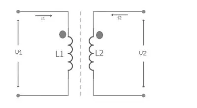
In the circuit employing dot convention, inductors L1 & L2 are mutually linked. Voltages V1 & V2 manifest across these inductors due to the current flowing through them, specifically across the terminals marked with dots.
Assuming the mutual inductance between these inductors is M, the induced voltage is calculated using the following formula:
For the primary inductor ‘L1’, the induced voltage ‘V1’ is determined as:

For the secondary inductor ‘L2’, the induced voltage ‘V2’ can be expressed as:

The above circuit features two types of induced voltage: one due to self-inductance and the other due to mutual inductance.
The voltage induced by self-inductance is calculated using the formula V = L(di/dt), which is positive (+ve). However, the voltage induced mutually can be negative (-ve) or positive (+ve) depending on winding construction and current flow. The dot notation plays a crucial role in determining the polarity of the mutually induced voltage.
Coupled-Inductor Analysis and Design
The design and analysis of coupled inductors can be explored through the implementation of a flyback converter circuit. This circuit is constructed using fundamental electronic components such as a coupled inductor (flyback transformer), a diode, a capacitor, and more.
The flyback converter circuit is a power supply configuration that relies on a coupled inductor to store energy when current flows through it. The stored energy is released once the power supply is disconnected. In terms of design and performance, these converters share similarities with booster converters, except that in the flyback arrangement, the primary winding of the transformer can be substituted with an inductor. Here, the secondary winding is responsible for delivering the output. Both windings in the flyback arrangement are employed as two distinct inductors.
Coupled Inductor Working & Operation
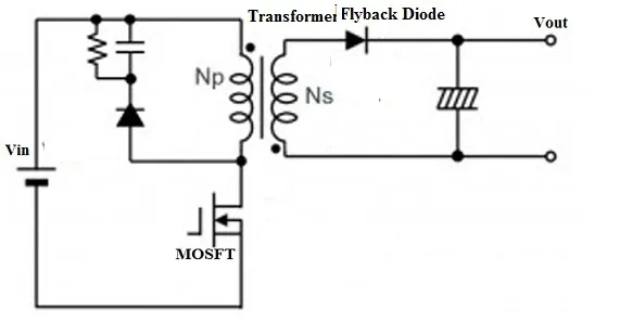
The flyback inverter circuit, illustrated below, features a flyback transformer with a gapped core, functioning as a coupled inductor. During each cycle, when the input voltage is applied to the primary winding, energy is stored within the core gap. Subsequently, this stored energy is transferred to the secondary winding to power the load. These transformers are crucial in flyback converters, facilitating voltage transformation and circuit isolation.
The fundamental principle of a flyback converter involves releasing the energy stored in a magnetic field when the flow of current through an inductor is interrupted, resulting in a sudden reversal of terminal voltage.
The flyback diode, connected across the inductor, serves to eliminate flyback, which occurs when a voltage surge is observed across the load due to the sudden interruption or reduction of current supply. This diode goes by various names like commutating diode, snubber diode, suppressor diode, freewheeling diode, catch diode, or clamp diode.
Typically, a MOSFET transistor acts as the switching device in a flyback converter circuit, controlled by a PWM signal to turn ON and OFF. The transformer's polarity is often reversed so that when the transistor is switched ON, current flows through the primary winding while the secondary diode is reverse-biased, preventing current flow in this winding.
Energy remains stored within the transformer until the transistor is turned OFF. As a result, the stored energy generates a current that forward-biases the diode, rectifying it to produce a DC output.
Flyback converters find applications in low-power TV sets, cell phone chargers, computers, high-voltage supplies in CRTs, lasers, copiers, xenon flashlights, among other devices.
Coupled Inductor Vs Transformer
| Coupled Inductor | Transformer | |
| The coupled inductor primarily serves to transfer energy from the primary winding to the secondary winding via a shared core. | A transformer's primary function is to transmit power from the primary winding to the secondary winding. | |
| A coupled inductor uses a gapped magnetic core to alter voltage between two coils, allowing controlled power transmission at specific intervals. | The transformer employs a magnetic core without a gap to modify the voltage between two coils and effectively transmit power in real-time. | |
| The coupled inductor consists of an air gap within its magnetic core. | The transformer doesn't incorporate an air gap within its construction. | |
| The coupled inductor doesn't have input power equaling its output power. | In a transformer, the input power is equal to the output power, maintaining a consistent energy balance. | |
| Energy storage within the core is achievable in a coupled inductor. | In a transformer, energy storage within the core is not a characteristic feature. | |
| It is utilized in DC to DC converters, such as the flyback converter, to reduce the voltage from 24V DC to 5V DC. | Transformers are used in AC to AC conversion scenarios, such as reducing the voltage from a standard wall outlet's 120VAC to 24VAC. |
Advantages
The advantages of a coupled inductor encompass several key aspects:
- Significant reduction in current ripple.
- Voltage conversion capabilities.
- Ability to modify circuit impedance.
- Galvanic isolation.
These advantages are particularly beneficial in switching power supplies, which utilize multiphase converters, SEPIC converters, galvanically isolated converters, and specialized circuitry to mitigate the adverse characteristics associated with hard switching.
Disadvantages
The disadvantages associated with coupled inductors are as follows:
- Slightly higher losses.
- Non-ideal operation within flyback converters.
- Changes in the current specifications of coupled inductors based on their series or parallel connections.
Applications
The applications of coupled inductors encompass a wide range of uses:
- Electrical applications frequently utilize coupled inductors.
- They are employed in power conversion circuits such as SEPIC, flyback, ZETA, Fly-Buck, Cuk, and multi-phase topologies.
- Their properties enable the adjustment of current and voltage, allowing for effective control.
- Coupled inductors are crucial for transferring impedance within circuits.
- They serve the purpose of electrically isolating two circuits from each other.
- The windings of coupled inductors can be configured in various setups to suit different needs.
- These inductors can be connected individually to circuits for applications like common-mode chokes and isolation transformers.
Related Articles
Inductor vs Resistor: What’s the Differences?
Understanding Coupled Inductors: Operations and Practical Applications
CBC3225T102KR Inductors: Features, Specifications, and Datasheet


