


Decoding Resistor Color Bands: A Beginner's Guide
I. Introduction to Resistor Color Bands
A common technique for indicating the resistance value, tolerance, and occasionally the temperature coefficient of resistors is the resistor color coding system. With this system, the resistor's surface is painted with colored stripes, each of which stands for a different coefficient or numerical value. Since resistors are the abecedarian corridor of virtually all electronic bias, it's pivotal for anyone dealing with electronic circuits to understand resistor color bars. It would be nearly hard to figure out the value of a resistor by simply looking at it if you did not know how to read these color bars. For this reason, it's essential for professionals, potterers, and suckers of electronics to learn this system.
II. Understanding the Color Code
A. Breakdown of the color bands and their significance
A resistor's color bars are crucial for displaying its resistance value, tolerance, and occasionally temperature coefficient. A resistor typically features four or five color bars, each of which stands for a different parameter. The first two bands indicate the significant digits of the resistance value, the third band represents the multiplier, and the fourth band denotes the tolerance. In some cases, a fifth band is used to represent the temperature coefficient.
B. How to interpret the resistance value, tolerance, and temperature coefficient
Interpreting the resistance value, tolerance, and temperature coefficient of a resistor involves decoding the color bands correctly. Here's how to interpret each component:
1. Resistance Value:
- The resistance value is determined by the first two color bands on the resistor.
- Each color represents a numeric value according to the following chart:
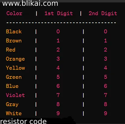
- For example, the resistance value is 27 if the first two bars are purple (7) and red (2).
2. Multiplier (Number of Zeros):
- The third color band represents the multiplier or the number of zeros that should be appended to the resistance value.
- Each color corresponds to a multiplier according to the following chart:
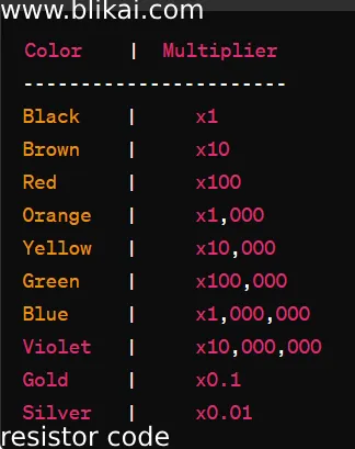
- For example, if the third band is orange (x100), the resistance value is multiplied by 100.
3. Tolerance:
- The fourth color band represents the tolerance or the percentage by which the actual resistance may vary from the stated resistance value.
- The tolerance is represented by the following colors:
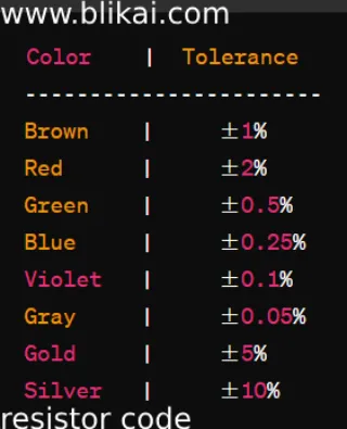
- For example, if the fourth band is gold (±5%), the resistance value may vary by ±5% from the stated value.
4. Temperature Coefficient (Optional):
- A fifth color band on certain resistors indicates the temperature coefficient.
- The resistance value of the resistor varies with temperature, as indicated by the temperature coefficient.
- The temperature coefficient is usually represented by the following colors:
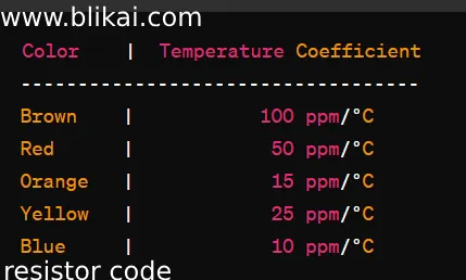
- For instance, the resistance varies by 10 parts per million for every degree Celsius that the temperature changes if the fifth bar is blue (10 ppm/°C).
III. Decoding the Color Bands
A. Step-by-step guide to reading resistor color bands
Resistor color bars must be decoded using a methodical approach that starts with determining each bar's color and ends with converting those colors into numerical values. First, determine the significant digits by identifying the colors of the first two bands. Next, determine the multiplier by identifying the color of the third band. Then, use these values to calculate the resistance value. Finally, identify the tolerance by examining the color of the fourth band. It is easier to determine the resistor value in an electronic circuit and more accurate interpretation of the resistor color bars if you follow this step-by-step tutorial.
B. Examples to illustrate the decoding process
Let's consider an example to illustrate the decoding process. Suppose we have a resistor with the color bands: yellow, violet, red, gold. Using the color code, we interpret this as follows:
Yellow (first band) = 4
Violet (second band) = 7
Red (third band) = 10^2 (multiplier)
Gold (fourth band) = ±5% (tolerance)
Combining these values, we find that the resistor has a resistance value of 47 10^2 ohms, with a tolerance of ±5%. These illustrations make the decoding process easier to understand, which makes it possible to estimate the resistor values in the electronic circuits with delicacy.
IV. Common Mistakes and Troubleshooting
A. Identification of common errors in decoding
In order to assure accurate estimation of resistance value, tolerance, and temperature coefficient, it is imperative to identify frequent faults in resistor color bar decoding. The following are typical mistakes to watch out for:
1. Misinterpreting Colors:
- Color blindness or inadequate lighting can lead to color misinterpretation.
- False readings can result from combining similar colors, such as red and orange or brown and red.
2. Misreading Color Code Sequence:
- Reading the color bands in the wrong order can lead to incorrect resistance values.
- Incorrectly identifying the first, second, or third bands can result in significant errors.
3. Overlooking Tolerance Band:
- Neglecting to identify or misidentifying the tolerance band can lead to discrepancies in the calculated resistance value.
- Tolerance is a crucial factor in determining the acceptable range of resistance.
4. Neglecting Temperature Coefficient (if present):
- Some resistors have a fifth band representing the temperature coefficient.
- Neglecting this band can lead to errors in determining how the resistance value changes with temperature.
5. Inaccurate Multiplier Interpretation:
- Incorrectly determining the multiplier band can result in errors in the order of magnitude of the resistance value.
- Choosing the wrong multiplier can lead to resistance values that are too large or too small.
6. Not Using a Reference Chart or Tool:
- Not having access to a resistor color code chart or tool can lead to errors in interpretation.
- Using an outdated or incorrect reference chart can also lead to misinterpretation of color bands.
B. Tips for troubleshooting and avoiding mistakes
To avoid common mistakes in decoding resistor color bands, several tips can be helpful. Firstly, ensure adequate lighting and visibility when inspecting the color bands to prevent misinterpretation of colors. Using a magnifying glass can also aid in distinguishing between similar colors, especially in smaller resistors. Double-checking the color code sequence and verifying the tolerance band can help catch any errors before finalizing the resistor value. Additionally, consulting a color code chart or using online resources can serve as a quick reference to confirm interpretations.

V. Practical Applications
1. Electronic Circuit Design:
- In electronic circuits, resistor color bars are used to measure the resistance of the resistors.
- Color coding is used by masterminds and amateurs to choose the applicable resistors for their circuits, guaranteeing the asked functionality.
2. Troubleshooting Electronic Circuits:
- By comprehending resistor color bars, professionals can diagnose electronic circuits effectively.
- Technicians can discover broken resistors and replace them with the correct values by decoding the color bars.
3. Repairing Electronic Devices:
- Resistor color canons are used by technicians to identify and replace imperfect resistors while fixing electronic outfit.
- It would be grueling to choose the applicable relief resistor if you did not know the color law.
4. Educational Purposes:
- Educational institutions employ resistor color bars to teach students about circuit design and electronic components.
- Students gain useful practical experience by learning how to compute resistor values and decipher resistor color bars.
5. DIY Electronics Projects:
- Resistor color coding is a useful tool for potterers and do- it- yourselfers working on a range of electronics systems.
- When opting the applicable factors, it's pivotal to comprehend resistor color coding, anyhow of whether you're constructing introductory LED circuits or further intricate electrical widgets.
VI. Conclusion
To sum up, everybody dealing with electronic circuits has to grasp resistor color coding. Color bars for resistors offer important details regarding its resistance, tolerance, and occasionally temperature coefficient. Engineers, technicians, and enthusiasts can choose the ideal resistors for their projects by precisely decoding these color bars, guaranteeing the best possible performance for electronic devices and circuits. Recall that the multiplier is represented by the third bar, the forbearance is shown by the fourth bar, and the significant integers are represented by the first two bars. Gaining an understanding of how to read these color bars is essential for determining resistor values directly and designing successful circuits.
FAQ
Q1: What do the colored bands on a resistor mean?
A resistor's resistance value, tolerance, and occasionally temperature coefficient are shown by its colored stripes. Every color has a corresponding multiplier or numerical value.
Q2: How many color bands are there on a resistor?
Resistors typically have four or five color bands. The first two bands represent the significant digits of the resistance value, the third band represents the multiplier, and the fourth band indicates the tolerance. In some cases, a fifth band is used to represent the temperature coefficient.
Q3: How do I read resistor color bands?
You must first determine each bar's color and then convert those colors into numerical values in order to interpret resistor color bars. Significant digits are represented by the first two bars, the multiplier by the third bar, and the tolerance by the fourth bar.
Q4: Why is it important to understand resistor color bands?
Understanding resistor color bands is pivotal for anyone working with electronic circuits. It allows you to directly determine the resistance value of a resistor, elect the right resistors for your systems, and troubleshoot electronic circuits effectively.
Q5: What are some common mistakes when decoding resistor color bands?
Common mistakes include misinterpreting colors due to poor lighting or color blindness, misreading the color code sequence, and overlooking or misidentifying the tolerance band.


