


10k Resistor Color Code: Everything You Need to Know

10k Resistor Color Code
If you are not familiar with the resistor color code methodology, you may find it difficult to interpret the colored bands on the cylindrical-looking shapes indicated by resistor values. Using the 10k resistor color code, we will explain how each band of the resistor is calculated and how each band compares to the others. Any person from the electronics or electrical field should be familiar with resistor color codes, so hopefully this article helps.
There are few resistors more commonly used in electronics than the 10K resistor. A resistor color code is best understood through its ubiquity. A strong advantage of having a quick way of distinguishing these resistors from their common counterparts in various projects is the ability to quickly identify them. Color coding is an essential tool for quickly identifying a 10K resistor's (10,000-ohm) resistance value and tolerance.
What is a 10k Resistor and its Color Code?
It is very useful to use 10k resistors as current controllers, even though they are passive resistors. This resistor has a resistance of 10,000 Ohms, hence the name 10k ohm resistor. The color band makes it easy to recognize.
10k Resistor Color Code
Four color rings are referred to as an ordinary precision color ring and five color rings are referred to as a precision color ring. A four-color ring resistor identifies its error with the fourth color ring. A gold color indicates a 5% error, while a silver color indicates a 10% error. When a resistor is constructed with five colors, the fifth color indicates the error, with brown indicating a 1% error, red indicating a 2% error, and green indicating a 0.5% error.
Resistor Color Code
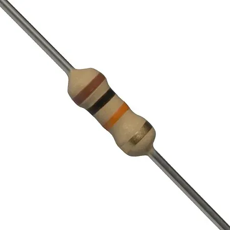
The above photo shows a ring resistor with four colors: brown, black, orange, and gold. The first two color rings on a four-color ring resistor indicate the resistor's effective value. Furthermore, the third color ring represents how many zeros are added to the effective value, while the fourth color ring represents the error. This color ring indicates the effective resistance value of the resistor and the error is 5%, since "brown, black" means "10", and "orange" means "10".
Applications of 10k Ohm Resistor
Due to its common usage in electronics, a 10k ohm resistor can be used across a wide range of fields. Some examples are as follows:
Voltage Feedback Network: Op-amps (operational amplifiers) usually have feedback resistors to determine their gain. It is possible to achieve specific voltage gains by using a 10k ohm resistor in the feedback network.
Timer Circuits: Multivibrators and astable multivibrators use resistors along with capacitors. Timing characteristics of such circuits can be adjusted with a 10k ohm resistor.
Voltage Regulators: A resistor provides feedback for regulating the voltage in linear voltage regulator circuits. The voltage regulation requirements of such applications may require a 10k ohm resistor.
Current Sensing: In motor control or battery management systems, resistors are often used to measure current. By measuring the voltage drop across a 10k ohm resistor, a voltage divider circuit can be used to indirectly measure current.
Temperature Sensors: Often, thermometers require a series resistor for interfacing with microcontrollers and analog-to-digital converters (ADCs) because they are temperature-sensitive resistors. Temperature sensing applications commonly use 10k ohm resistors.
Filter Circuits: A passive filter circuit is constructed using resistors and capacitors. It is possible to use 10k ohm resistors as low-pass, high-pass, band-pass, or band-stop filters, according to the circuit configuration.
Voltage Divider: Circuits with voltage dividers are among the most common applications. By connecting two resistors in series, one can construct a voltage divider. By dividing the input voltage by two resistors, we determine the resistance ratio. Reference voltages can be created with this method, biasing circuits can be created, and voltages can be scaled down for measurement purposes.
Pull-up or Pull-down Resistors: Often, 10k ohm resistors are used as pull-up or pull-down resistors when using digital inputs. Microcontrollers and integrated circuits (ICs) use these resistors to ensure that inputs remain stable even when no active signals are present.
LED Current Limiting: In order to prevent LEDs from being damaged, current must be limited when driving them with a voltage source. LEDs can be controlled by using 10k ohm resistors in series to limit their forward voltage and supply voltage to a safe range.
Biasing Transistors: 10k ohm resistors are usually used to bias transistors in transistor circuits, including common-emitter amplifiers. Transistor amplifier circuits are linearized and operated at their operating points by these resistors.
How to Read Resistor Color Code?
You can easily determine the value of a resistor by interpreting its color bands. Color coding resistors was a valuable invention dating back to the early 1920s due to the impracticality of printing alphanumeric codes on tiny resistors.
When reading the resistor color code, one of the most common questions is where to begin. There are a few visual cues that can provide you with assistance:
Band Grouping: In most cases, resistors don't have evenly spaced color bands. Bands are usually grouped according to a certain pattern, and there is usually a gap between them. Before the tolerance band, there is the largest gap. Read the resistor from left to right by placing this broader group on the left.
Tolerance Marker: A resistor usually has a tolerance of 5% or 10%. A gold color indicates a tolerance of 5%, while a silver color indicates a tolerance of 10%. It is important to note that resistor color codes never start with metallic colors. On the right side of the resistor, you can see the tolerance values unambiguously. One more time, read the resistor from left to right.
Starting Band: The first band is generally closest to the resistor's end, but it is not an absolute rule. You can confirm the starting point using other clues if you are unsure.
To determine which resistance is likely to be present, use a multimeter to determine which resistance may be present and read directions accordingly. The following steps will help you read the resistor color code:
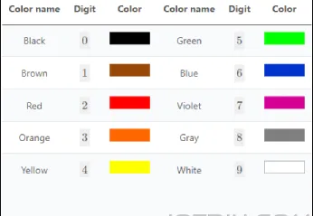
Each color represents a specific number, denoting the resistance value:
Sequence of Color Code
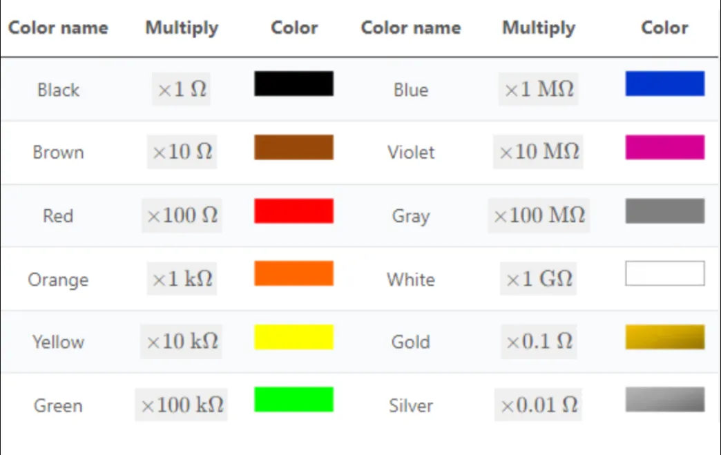
Color codes are implemented on the left side's first two or three bands. We arrive at the multiplier band following these initial bands, which is distinguished by the following color codes:
Multiple Bands Color Code
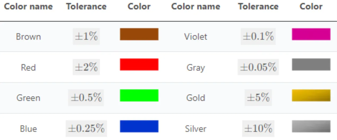
By multiplying the number derived from the preceding bands by each color, the number derived from the preceding bands is multiplied by a power of 10. The prefixes kilo, mega, and giga are used to represent these multipliers. Alternatively, small units can be expressed in scientific notation, such as 10 9 (gigaohm). All resistor types have a tolerance band that appears on the last color band (4, 5, and 6). Typically, this represents a normal distribution of component resistance expressed in percentages:
Different Color Bands
The interpretive colors are the same for 4 and 5-band resistors. A separate section discusses the temperature coefficient on 6-band resistors. The resistor also has an additional band indicating the temperature coefficient.
Faqs
Question 1: How to read the color bands on a 10k resistor?
Answer: By reading the bands left-to-right, you can determine the value of a 10k resistor. Significant digits are represented by the first two bands, multipliers by the third band, and tolerance by the fourth band.
Question 2: Can the color bands vary for a 10k resistor?
Answer: There are a variety of colors available in 10k resistors, including brown, black, orange, and gold. Depending on the region and the specialty resistor, other specifications could differ. It is most commonly recognized that 10k ohm resistors should be numbered brown-black-orange-gold.
Question 3: Can resistor color bands be decoded with tools or apps?
Answer: The resistance color bands of resistors can be decoded with a great deal of accuracy and speed with the use of online tools, mobile apps, and handheld devices. Especially when dealing with precision resistors with tighter tolerances of resistors with multiple bands, these tools can prove useful.
Question 4: Is a multimeter capable of measuring a 10k resistor's resistance?
Answer: An accurate measurement of 10k resistor resistance can be made with a multimeter. The probes should be connected to both ends of the resistor, with the multimeter set to the resistance (ohms) measurement mode. Resistance values will be displayed on the multimeter.
Final Verdict
For accurate resistance measurement, it is important to understand the color code of a 10k ohm resistor. A resistor's resistance and tolerance can be determined by using the standard color bands of brown, black, orange, and gold.
You can easily determine without interpreting the color bands that a brown-black-orange-gold resistor has a resistance of 10,000 ohms (10k ohms) with a tolerance of +/- 5%. By gaining this knowledge, you will be able to select and use 10k resistors in a variety of electronic circuits and applications confidently.
While variations in color coding may exist in certain cases, especially with specialty resistors or different regional standards, the sequence of brown-black-orange-gold remains prevalent and reliable for identifying 10k resistors in most scenarios. Overall, mastering the 10k resistor color code empowers electronics enthusiasts, hobbyists, and professionals alike to effectively incorporate these fundamental components into their projects with precision and accuracy.


