


What is a High Pass Filter? Features, and Applications
In a bygone era, making a telephone call across long distances required one to speak slowly and loudly into the transmitter, ensuring clarity for the recipient at the other end. Nowadays, we can effortlessly conduct video calls globally with high-resolution quality. The remarkable advancement in technology owes much to Electrical Filter Theory and Transmission Line Theory. Electrical filters function as circuits that selectively allow certain frequency bands to pass through while suppressing undesired frequencies. An example of such a filter is the High Pass Filter.
What is a High Pass Filter?
The most basic form of a high-pass filter is known as the "first-order high-pass filter". Its behavior is typically described by a first-order linear differential equation. Its left-hand side closely resembles that of a first-order low-pass filter, with the only difference lying in the right-hand side, which features the derivative of the input signal rather than the signal itself. When a signal with lower frequencies traverses the system, the output is minimal or nonexistent, whereas higher frequencies experience less attenuation.
Essentially, at extremely high frequencies, a capacitor behaves like a "short circuit", allowing these frequencies to pass through the resistor virtually unimpeded. Thus, the system is adept at transmitting high frequencies while impeding low frequencies, making it the simplest form of a "high-pass filter".
The operational principle of this circuit is as follows: when the frequency is below the cutoff frequency (f), the input signal passing through capacitor C1 is hindered due to its substantial capacitive reactance, resulting in reduced output—wherein lower frequencies yield progressively diminished output. Conversely, when the frequency surpasses f, the signal encounters minimal attenuation as the capacitive reactance of C1 diminishes, thereby allowing high-frequency signals to pass through while blocking low-frequency signals. The corner frequency (f) of this circuit is determined by the following formula:
_of_this_circuit.webp)
Apart from using components, high-pass filters can also be constructed using LC components.
High Pass Filter Circuit
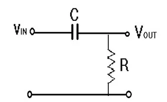
The fundamental High Pass Filter circuit consists of a series connection of a capacitor and a resistor. The input signal is applied across the capacitor, while the output is taken from across the resistor.
High Pass Filter Circuit
In this circuit configuration, the capacitor exhibits high reactance at lower frequencies, functioning as an open circuit for low-frequency input signals until reaching the cutoff frequency 'fc'. Consequently, the filter attenuates all signals below this cutoff frequency level. As the frequency surpasses the cutoff frequency, the capacitor's reactance diminishes, essentially acting as a short circuit for these frequencies, allowing them to pass directly to the output.
Passive RC High Pass Filter
The aforementioned High Pass filter is commonly referred to as a Passive RC High Pass filter due to its reliance solely on passive components. External power is unnecessary for the filter's operation. In this setup, the capacitor serves as the reactive element, with the output drawn across the resistor.
High Pass Filter Features
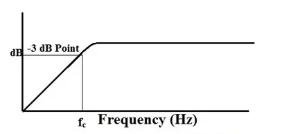
The cutoff frequency denotes the point in the filter's frequency response where the gain equals 50% of the peak gain of the signal, also known as 3dB of the peak gain. In a High Pass Filter, gain amplifies with increasing frequencies.
High Pass Filter Frequency Curve
The cutoff frequency (fc) relies on the R and C values within the circuit. The time constant (τ) is expressed as the product of R and C, with the cutoff frequency being inversely proportional to the time constant.
Cutoff frequency = 1/(2πRC)
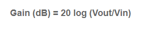
The circuit gain is defined as AV = Vout/Vin, where AV = (Vout)/(Vin) = R/√(R^2 + Xc^2) = R/Z.
At low frequencies (f), Xc approaches infinity, resulting in Vout = 0.
At high frequencies (f), Xc approaches 0, leading to Vout = Vin.
Frequency Response of a High Pass Filter or High Pass Filter Bode Plot
In a high pass filter, frequencies below the cutoff frequency ('fc') are attenuated. At the cutoff frequency, we observe a gain of -3dB, where the reactance of the capacitor and resistor are equal, i.e., R = Xc. The gain is calculated as:
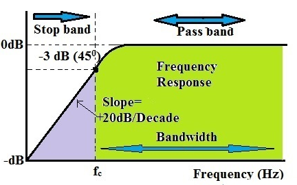
The slope of the high pass filter curve is +20 dB per decade. This signifies that after surpassing the cutoff frequency, the output response of the circuit ascends from 0 to Vin at a rate of +20 dB per decade, equivalent to a 6 dB increase per octave.
High Pass Filter Frequency Response
The section from the starting point to the cutoff frequency is termed as the stop band, where no frequencies are permitted to pass. Conversely, the area beyond the cutoff frequency, specifically the -3 dB point, constitutes the passband. At the cutoff frequency, the output voltage amplitude equals 70.7% of the input voltage.
The bandwidth of the filter signifies the range of frequencies through which signals are permitted to pass. For instance, if the high pass filter has a bandwidth of 50 kHz, it implies that only frequencies from 50 kHz to infinity are permitted.
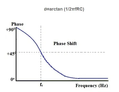
At the cutoff frequency, the phase angle of the output signal is +45 degrees. The formula to compute the phase shift of a high pass filter is:
In practical scenarios, the output response of a filter doesn't extend infinitely due to limitations imposed by the electrical characteristics of the filter elements. Through careful selection of filter components, we can customize the range of frequencies to be attenuated or passed.
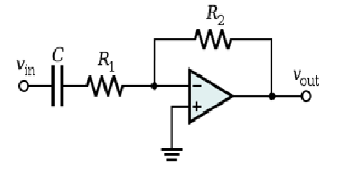
High Pass Filter with Op-Amp
In this configuration, an op-amp is integrated into the high pass filter alongside passive filter elements. Unlike obtaining an infinite output response, the output response here is constrained by the open-loop characteristics of the op-amp. Consequently, this filter operates as a band-pass filter, with the cutoff frequency determined by the bandwidth and gain characteristics of the op-amp.
The open-loop voltage gain of an op-amp serves as a constraint on the bandwidth of the amplifier. As the input frequency increases, the gain of the amplifier decreases to 0 dB. The circuit's response resembles that of a passive high pass filter, but here, the op-amp's gain amplifies the output signal's amplitude.
The gain of the filter utilizing a non-inverting op-amp is expressed as:
AV = Vout/Vin = (Af (f/fc))/√(1+ (f/fc)^2 )
where:
Af denotes the passband gain of the filter, calculated as 1+( R2)/R1
f represents the input signal frequency in Hz
fc denotes the cutoff frequency
When low-tolerance resistors and capacitors are utilized, these Active High Pass filters offer reliable accuracy and performance.
Active High Pass Filter
The usage of an op-amp in conjunction with passive components like capacitors and resistors renders the High Pass Filter as an active high pass filter. This integration of an active component allows for the precise control of the filter's cutoff frequency and output response range.
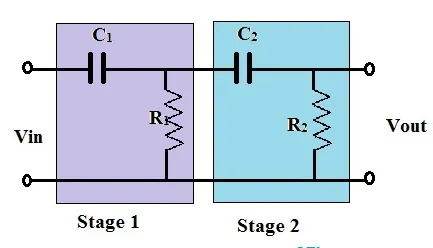
Second Order High Pass Filter
The filter circuits previously discussed are all categorized as first-order high pass filters. In a second-order high pass filter, an additional RC network block is introduced into the input path of the first-order high pass filter.
The frequency response of the second-order high pass filter closely resembles that of the first-order variant. However, in the second-order high pass filter, the stop band is twice as wide as that of the first-order filter, attenuating at a rate of 40dB/Decade. Higher-order filters can be created by cascading first and second-order filters. While there's no theoretical limit to the order, higher-order filters lead to larger filter sizes and a degradation in accuracy. In a higher-order filter where R1 = R2 = R3, and C1 = C2 = C3, etc., the cutoff frequency remains constant regardless of the filter's order.
High Pass Filter Transfer Function
Due to the varying impedance of the capacitor, electronic filters exhibit a frequency-dependent response.
The complex impedance of a capacitor is represented as Zc = 1/sC
Where, s = σ + jω, with ω denoting the angular frequency in radians per second.
The transfer function of a circuit can be determined using standard circuit analysis techniques such as Ohm’s law, Kirchhoff’s Laws, Superposition, etc. The general form of a transfer function is expressed by the equation:
H(s) = (am s^m + a(m-1) s^(m-1) + ⋯ + a0) / (bn s^n + b(n-1) s^(n-1) + ⋯ + b0)
The order of the filter corresponds to the degree of the denominator. The poles and zeros of the circuit are obtained by solving the roots of the equation, which may consist of real or complex roots. The plotting of these roots on the s-plane, where σ represents the horizontal axis and ω the vertical axis, provides valuable insights into the circuit. For a high pass filter, a zero is located at the origin.
The transfer function for a high pass filter can be expressed as:
H(jω) = Vout/Vin = (-Z2(jω))/(Z1(jω))
= – R2 / (R1 + 1/jωC)
= -R2/R1 * (1 / (1 + 1/(jωR1C)))
Here, H(∞) = R2/R1, representing the gain as ω approaches infinity.
τ = R1C and ωc = 1/τ, where ωc = 1/(R1C) denotes the cutoff frequency.
Thus, the transfer function of a high pass filter is given by:
H(jω) = – H(∞)(1 / (1 + 1/jωτ))
= – H(∞)(1 / (1 - (jωc)/ω))
When the input frequency is low, Z1(jω) is large, resulting in a low output response.
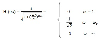
H(jω) = (-H(∞)) / √(1 + (ωc/ω)^2) = 0 when ω = 0; H(∞) / √2 when ω = ω_c; and H(∞) when ω = ∞. The negative sign indicates a phase shift.
When R1 = R2 and s = jω, H(0) = 1.
Thus, the transfer function of a High Pass Filter H(jω) = jω / (jω + ω_c).
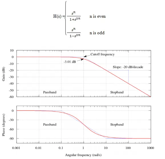
Butterworth High Pass Filter
An ideal filter should not only reject unwanted frequencies but also maintain uniform sensitivity for desired frequencies. While such an ideal filter is impractical, Stephen Butterworth proposed in his paper "On the theory of filter amplifiers" that this type of filter could be achieved by increasing the number of appropriately sized filter elements.
The Butterworth filter is designed to provide a flat frequency response in the filter's passband and attenuate towards zero in the stop band. Although the basic prototype is a low pass design, modifications can yield high pass and bandpass filters.
For a first-order high pass filter, the unit gain is expressed as H(jω) = jω / (jω + ω_c).
For n such filters in series, H(jω) = (jω / (jω + ω_c))^n, which upon solving yields:
‘n’ dictates the degree of transition between the pass band and stop band. Consequently, a higher order corresponds to a more rapid transition. Therefore, when n = ∞, the Butterworth filter transforms into an ideal High Pass Filter.
During the implementation of this filter, for simplicity, we set ωc = 1 and solve the transfer function for s = jω. In other words, H(s) = s / (s + ωc) is simplified to H(s) = s / (s + 1) for order 1.
For order 2, the transfer function becomes H(s) = s^2 / (s^2 + Δωs + (ωc^2)).
Thus, the transfer function of the cascade in the High Pass Filter is:
Applications of a High-Pass Filter
A prevalent application of this passive filter is found in audio amplifiers, where it serves as a coupling capacitor linking two audio amplifier stages, and in speaker systems to channel higher frequency signals towards smaller "tweeter" type speakers. It effectively blocks lower bass signals or serves as a filter to diminish low-frequency noise or "rumble"-type distortion. In audio contexts, high-pass filters may alternatively be termed as "low cut" or "bass switching" filters.
In power systems, high-pass filters are utilized to eliminate harmonics of a certain order and above during harmonic compensation. Low-pass filters are employed to drive subwoofers and other loudspeakers while blocking signals that tweeters cannot effectively handle. High-pass filters ensure high-frequency sounds are directed to dedicated tweeters, while also preventing bass signals from interfering with or damaging the speakers. Similarly, a low-pass filter using a coil instead of a capacitor can concurrently direct low-frequency signals to the woofer. This setup is commonly known as an audio crossover.
Moreover, high-pass and low-pass filters play crucial roles in digital image processing for frequency domain transformations.


