


Exploring Band Reject Filters: Theory and Applications
I. Introduction
An essential part of signal processing, band reject filters are made to attenuate or reject a certain frequency band while letting the rest pass. Often referred to as band reject filters, they are widely used in many different domains such as radio frequency communications, biomedical signal analysis, and sound processing. This article's goal is to give readers a thorough understanding of band reject filters—from their foundational theory to useful design examples—so they can apply them successfully in signal processing applications.
II. Fundamentals of Band Reject Filters
A. Explanation of band reject filters
In signal processing, reject filters, also known as band reject filters, are an essential instrument. They are made to reject or reduce a particular band while passing through all frequencies. Unlike other types of filter like low- pass, high- pass, or band reject filter, which let certain frequentness pass while blocking others, band reject filter target a specific frequence range for attenuation.
B. Comparison with other types of filters (e.g., low-pass, high-pass, band-pass)
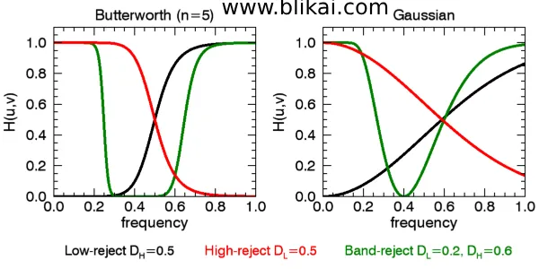
When band reject filters are compared to other filter types, we discover that low pass filters permit frequencies below a specific limit to pass, whereas high pass filters attenuate higher frequencies while allowing higher frequencies to pass. band reject filters, on the other hand, pass only that range of frequencies through attenuation of all other frequencies.
C. Basic components and operation principles
Inductors, capacitors, and resistors are the standard parts of a band reject filter. These filters work on the basis of building a circuit that, at frequencies outside the desired range, generates a low impedance channel, thereby blocking those frequencies and permitting comparatively unattenuated frequencies to flow through. The center frequency, bandwidth, and attenuation qualities of the filter are all determined by the precise arrangement of these constituent parts. Comprehending these fundamental concepts is imperative for the creation and utilization of band reject filters in diverse signal processing scenarios.
III. Types of Band Reject Filters
A. Active Band Reject Filters
- Description
Active band reject filter use active factors similar as functional amplifiers to achieve frequence rejection. These filter are able of furnishing high situations of attenuation with low insertion loss. Typically, active band reject filters are implemented using multiple feedback (MFB) or Sallen-Key topologies.
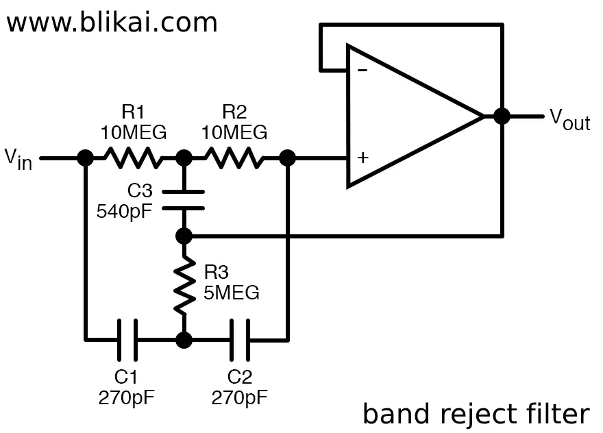
- Circuit diagrams
Active band reject filter circuits often contain operational amplifiers, resistors, capacitors, and occasionally inductors. The configuration of these rudiments determines the center frequence, bandwidth, and attenuation parcels of the filter.
- Advantages and disadvantages
Low insertion loss, good attenuation, and ease of center frequence and bandwidth tuning are the benefits of active band reject filter. But they need a power source and can distort and add noise to the signal.
B. Passive Band Reject Filters
- Description
Passband rejection filters, sometimes referred to as notch filters, attenuate particular frequency ranges by means of passive parts like resistors, capacitors, and inductors. These filters are rather easy to apply and don't require a power supply.
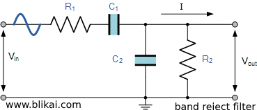
- Circuit diagrams
The primary band rejection filter are designed with resistors, capacitors, and inductors to give a cut- off at the necessary frequence.
- Advantages and disadvantages
The following benefits of unresistant bypass filter are their simplicity, affordability, and lack of power force. When compared to active filters, they might, however, be less successful at producing high attenuation and have a greater insertion loss.
IV. Design Considerations
A. Frequency range and bandwidth:
The rejection filter's bandwidth and frequency bandwidth decide the range of frequencies that need to be muted. To satisfy the demands of the particular application, critical parameters like rejection band center frequency and rejection bandwidth must be properly chosen.
B. Q factor:
The band rejection filter's Q-factor, also known as the quality factor, controls how acute the slit is at the rejection frequency. A shorter rejection zone and a steeper rejection frequency surrounding it are the outcomes of a greater Q-factor. The ratio of the rejection bandwidth to the center frequency is used to compute the Q-factor.
C. Impedance matching:
To reduce signal reflections and provide optimal power transfer within the filter band, impedance matching is crucial. Signal distortion and loss can be avoided if the filter's input and output, as well as any connected equipment, have the appropriate impedance matching.
D. Selecting components:
Achieving the intended performance characteristics of a band reject filter requires careful component selection. When choosing resistors, capacitors, and inductors, factors including forbearance, temperature stability, and frequence characteristics must be taken into account. also, the intended filter center frequence, bandwidth, and Q- factor must be taken into account when calculating the values of these factors.
V. Applications of Band Reject Filters
A. Signal interference reduction:
Unwanted signals or noise can interfere with desired signals in many electrical systems. Band reject filters are frequently used to attenuate particular interference frequencies, which efficiently reduces noise and enhances the quality of the intended signal.
B. Notch filtering in audio applications:
Band reject filters are commonly employed in sound systems to eliminate precipitates, or certain frequencies, such buzzing or humming brought on by background noise or electrical interference.
C. RF communication systems:
In order to reject undesired signals or interference at specific frequencies and let desired RF signals get through with the least amount of attenuation, band rejection filters are crucial parts of RF communication systems.
D. Biomedical signal processing:
In biomedical signal processing, band- pass filter are used to exclude undesirable noise and hindrance from signals, including electrocardiograms( ECGs) and electromyograms( EMGs), allowing for more precise analysis and opinion. These filter aid in enhancing the quality and signal- to- noise rate of biomedical data in clinical operations.
VI. Design Examples
Example 1: Active Band Reject Filter for audio applications
An active band rejection filter is commonly used in audio applications for rejection filtering, which removes frequencies like hum that are produced by electrical interference (e.g., 50 Hz or 60 Hz).
The active- band rejection filter circuit is frequently formed by functional amplifiers arranged in a Sallen- Key or multiple feedback( MFB) topology, along with resistors and capacitors.
For case, when erecting a 50 Hz active band rejection filter for audio operations, the rejection band is set to a center frequence of 50 Hz and a narrow bandwidth to insure effective junking of uninvited frequentness while minimizing the effect on the asked sound. hum. signals.
Example 2: Passive Band Reject Filter for RF communication systems
Passive band rejection filters are crucial in radio frequency (RF) communication systems because they block undesirable signals or interference at specific frequencies while letting the intended RF signals through.
In order to produce a dip at an undesirable frequency, a combination of capacitors and inductors is usually placed in a predefined configuration as the passive rejection filter in RF communications systems.
In order to reject 2.4 GHz signals, for instance, a passive band reject filter for a Wi-Fi system would need to be designed such that it creates a dip at 2.4 GHz while leaving other frequencies largely unaffected.
VII. Conclusion
To sum up, band reject filters, also known as cut filters, come in two flavors unresistant and active. Whereas unresistant filter make use of inductors, capacitors, and resistors, active filter use functional amplifiers. Design aspects include element selection, Q- factor, frequence response, bandwidth, and impedance matching.
FAQ
1. What is a band reject filter?
frequently called a low- pass filter, is a kind of electronic filter that rejects or attenuates a specific frequence range while allowing all other frequentness to go through.
2. How does a band reject filter work?
In order to efficiently block frequencies outside of the desired range and allow frequencies inside the desired range to flow through relatively unsuppressed, a band reject filter creates a circuit with low resistance at certain frequencies.
3. What are the types of band reject filters?
Two primary categories of band reject filters exist:
- Active band rejection filters: these filters make use of operational amplifiers and other active parts.
- Passive band rejection filters: resistors, capacitors, and inductors are examples of passive parts used in these filters.
4. What are the applications of band reject filters?
Band reject filters find applications in various fields, including:
- Signal interference reduction
- Notch filtering in audio applications
- RF communication systems
- Biomedical signal processing
5. How do I choose the right band reject filter for my application?
When choosing a band reject filter, consider factors such as:
- Frequency range and bandwidth
- Q factor
- Impedance matching
- Selecting components
6. Can band reject filters be used in combination with other filters?
In order to produce more complex filtering functions, band reject filters can be used in combination with other filters like low- pass, high- pass, or band reject filters.
7. What are the advantages of using band reject filters?
Some advantages of band reject filters include:
- Effective rejection of unwanted frequencies
- Improved signal-to-noise ratio
- Versatility in signal processing applications
8. What are the disadvantages of band reject filters?
Some disadvantages of band reject filters include:
- Insertion loss
- Possible signal distortion
- Complexity in design and implementation
9. Are there any future trends in band reject filters?
Future developments in band reject filters will likely focus on creating designs that are more efficient, adaptable, and compact in order to satisfy the changing needs of contemporary signal processing applications.
10. Where can I find more information about band reject filters?
Electronics textbooks, online sites, and technical literature all contain additional information regarding band reject filters. Furthermore, seeking advice from seasoned scientists or engineers in the area can yield insightful information.


