


FIR Filters:Overview,Structure and Signal Processing
In the realm of digital signal processing, an FIR filter is characterized by its finite impulse response, meaning its response diminishes to zero within a finite timeframe. This sets it apart from IIR filters, which can sustain responses due to internal feedback. The impulse response of an FIR filter of order N concludes after precisely N+1 samples. FIR filters reign as the favored filter type in software implementation, encompassing continuous-time, analog, digital, and discrete-time varieties. Notable variants of FIR filters include the Boxcar, Hilbert Transformer, Differentiator, Lth-Band, and Raised-Cosine filters.
What is FIR Filter?
The acronym FIR stands for "Finite Impulse Response," representing one of the primary types of digital filters employed in DSP applications. Filters serve as signal conditioners, with their main function being to permit AC components while obstructing DC components. A familiar example illustrating this function is a phone line, which effectively acts as a filter by constraining frequencies to a range considerably narrower than what humans can audibly perceive.
FIR Filters in Digital Signal Processing
In the realm of digital signal processing, there exists a diverse array of filters, including LPF, HPF, BPF, and BSF. LPF, or Low Pass Filter, selectively permits only low-frequency signals through its output, making it ideal for attenuating high-frequency components. LPF proves particularly useful for managing the upper spectrum of frequencies in audio signals. Conversely, HPF, or High Pass Filter, functions in opposition to LPF by excluding frequency components below a specified threshold. A quintessential application of HPF is in eliminating the 60Hz audible AC power, a common source of noise in signals across the USA.
In the realm of DSP, an alternative to FIR filters is the IIR filter, which employs feedback mechanisms. When an impulse is introduced as input to an IIR filter, theoretically, the output resonates indefinitely. Key terms associated with IIR filters include Tap, impulse response, MAC (multiply accumulate), delay line, transition band, and circular buffer.
Design Approaches for FIR Filters
The design methodologies for FIR filters hinge on the approximation of an ideal filter. As the filter's order escalates, it progressively approximates the desired characteristics, albeit at the expense of increased complexity in both design and implementation.
The design journey commences with outlining the requirements and specifications for the FIR filter. The selection of a specific design method is contingent upon the filter's intended implementation and specified criteria. Each design method carries its own set of advantages and disadvantages, underscoring the importance of a judicious choice.
Given the efficiency and simplicity inherent in FIR filters, the window method emerges as a popular choice. Alternatively, the sampling frequency method offers simplicity as well, albeit with a minor compromise in stopband attenuation.
Logical Structure of FIR Filter
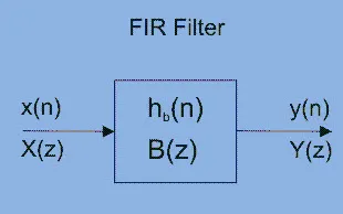
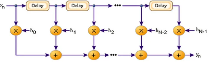
In digital signal processing, a FIR filter serves as a versatile tool for realizing a broad spectrum of digital frequency responses. Typically, these filters are crafted using a combination of multipliers, adders, and a sequence of delays to generate the desired output. Illustrated below is the fundamental diagram of a FIR filter with a length of N. The output results from the delayed samples, each multiplied by corresponding coefficients (hk), culminating in their summation.
Logical Structure of FIR Filter
Filter design entails the meticulous selection of the filter's length and coefficients, aimed at achieving specified parameters such as stopband and passband characteristics. MATLAB software is commonly employed by engineers for this purpose.
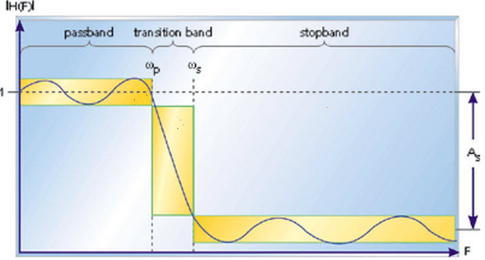
Filters are often characterized by their responses to distinct frequency components present in the input signal. These responses are categorized into three types based on frequency: stopband, passband, and transition band. The passband response reflects the filter's influence on frequency components that remain largely unaffected. Conversely, frequencies within the stopband are substantially attenuated. The transition band encompasses frequencies that undergo some reduction but remain integrated with the output signal.
Frequency Response Characteristics of an FIR Filter
Below is a depiction of the frequency response plot of the filter, with ωp denoting the passband endpoint frequency, ωs indicating the start of the stopband, and As representing the level of attenuation in the stopband. Frequencies lying between ωp and ωs constitute the transition band, where attenuation occurs to a lesser extent. This validates that the filter conforms to the specified requirements, encompassing parameters such as transition bandwidth, ripple, filter length, and coefficients.
The lengthier the filter, the finer the response can be finely tuned. With the filter's length denoted as N and coefficients defined as an array h[N] = {…}, the implementation of the FIR filter is relatively straightforward.
Frequency Response of an FIR Filter
Z Transform of an FIR Filter:
In the context of an N-tap FIR filter characterized by coefficients h(k), the output y(n) is expressed as:
\[ y(n) = h(0)x(n) + h(1)x(n-1) + h(2)x(n-2) + \ldots + h(N-1)x(n-N-1) \]
The Z-transform representation of the filter is given by:
\[ H(z) = h(0)z^{-0} + h(1)z^{-1} + h(2)z^{-2} + \ldots + h(N-1)z^{-(N-1)} \]
Alternatively,
Transfer Function of FIR Filter:
The transfer function of the FIR filter is encapsulated by its Z-transform representation.
Frequency Response Formula for an FIR Filter:
The frequency response of the FIR filter is derived from its transfer function or Z-transform.
DC Gain of an FIR filter:
The DC gain of the FIR filter refers to its response at zero frequency, often expressed as the value of H(z) when z = 1.
Applications of FIR Filters:
FIR filters find extensive applications in digital communications, particularly in the intermediate frequency stages of receivers. For example, in digital radios, the analog signal is first received and converted to intermediate frequency before being digitized using a digital-to-analog converter. FIR filters are then utilized to select the desired frequency components. They are also integral to software radios, enabling the facile adjustment of filters with robust rejection capabilities without necessitating hardware modifications.
In summary, we've covered various aspects of FIR filters, including their design methods, logical structure, frequency response characteristics, and applications. We hope this has provided you with a clearer understanding of the concept. If you have any questions or would like to discuss further, please feel free to leave your queries and comments in the comment section below.
Now, let's address your question about the difference between FIR and IIR filters
FIR (Finite Impulse Response) filters:
- FIR filters have a finite impulse response, meaning their output settles to zero after a finite number of samples.
- They do not utilize feedback loops, making them inherently stable and linear phase.
- FIR filters are often easier to design, implement, and understand compared to IIR filters.
- However, they typically require more computational resources and have a longer latency.
IIR (Infinite Impulse Response) filters:
- IIR filters have an infinite impulse response, meaning their output can persist indefinitely due to feedback loops.
- They can achieve similar filtering characteristics as FIR filters with fewer coefficients, making them computationally efficient.
- IIR filters are prone to instability if not designed properly, and they may exhibit nonlinear phase characteristics.
- Designing IIR filters can be more complex, especially ensuring stability and meeting specifications.
In essence, the main difference lies in the impulse response and feedback mechanism employed by each type of filter, resulting in distinct characteristics and trade-offs in terms of stability, computational efficiency, and design complexity.


