


How to Test a Diode: A Step-by-Step Guide with Multimeter
What is a Diode?
A diode is the essential electronic component that will allow the current to flow in one direction, blocking in the other. Due to this unique nature, the diodes are very important for many semiconductor and electronic circuits. A diode mainly consists of two pieces of semiconductor materials. Usually, these are silicon or germanium, being joined together, thus forming the so-called P-N junction.

How Diodes Work
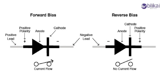
Forward Bias
In as much as the anode of the diode is now connected to the positive terminal of a power source, whereas the cathode is attached to the negative terminal of the power source, the current can now flow easily through this diode. The decrease in the applied voltage exceeds the possible barrier in the area, able to transfer electrons from N-type content to P-type content.
Reverse Bias
Reverse bias occurs when the anode of the diode is connected to a negative terminal and a positive terminal to the cathode. In this state, the reduction area becomes wide, which increases the potential barrier. As a result, the diode blocks the current flow, acting as an open switch. Only a minimum leak current passes through a diode in reverse bias.
Breakdown Voltage
Each diode contains a prescribed reverse breakdown voltage. The reverse voltage applied to the diode exceeds this range, and thus, the diode works in the breakdown mode. In breakdown, the diode conducts current in the reverse direction, which could damage the device when not adequately controlled. Some special diodes, like Zener diodes, are designed to operate in the breakdown area for voltage regulation purposes.
Diodes Common Applications
LEDs and Displays
LEDs form the most widely known application of the diode. This versatile component is used to power everything from indicator lights on electronics to mass displays and even modern lighting solutions. With energy efficiency, long life, and the ability to produce a broad spectrum of color, LEDs have found various applications in the world.
Power Supplies and Voltage Regulation
A rectifier diode is responsible for converting optional current (AC) into ulterior direct current (DC), which is vital to the operation of many electronic devices. Zener diodes, on the contrary, are used for voltage regulation, an essential aspect of many electronic devices, permitting to keep the same voltage level in a circuit, notwithstanding what happens with the input voltage or load current.
Signal Processing and Protection
In signal processing, diodes are used to shape and modify waves. For example, clippers use diodes to limit the circuit signal dimensions, while clamper circuits transfer the DC level of a signal. The diodes also serve as safety devices in many circuits, prevent reverse current flows and protect sensitive components from voltage spikes.
Solar Panels and Energy Harvesting
Solar panels rely too much on the diode for their functionality. Each of the solar cells functions like a large-area diode that converts light energy into electrical energy. In addition, a bypass diode is there to maintain efficiency in the solar panel should individual solar cells become shaded or damaged.
How to Test a Diode with a Digital Multimeter
Setting Up Your Digital Multimeter
Before you conduct your diode testing, check to see whether your digital multimeter is set to the diode test mode. A diode symbol on the multimeter dial will generally indicate this mode. If your multimeter does not have a specific diode mode, set it to the lowest resistance range, typically around 200 ohms.
Identifying Diode Leads
Find the lead of the cathode (negative) and anode (positive) diode. The cathode is usually marked with a band or bandage. This step is essential for appropriate testing.
Connecting the Probes
Connect the red probe of the multimeter to the diode's anode (positive end) and the black probe to the cathode (opposing end). Ensure a firm relationship between the investigation and the diode lead.
Reading the Results
A working diode should show a forward voltage drop between 0.5 to 0.7 volts for a silicon diode. If your multimeter "OL" (more than the border) or displays very high resistance, reverse the probe. One suitable diode should be operated in one direction and not the other.
Reverse Polarity Test
Swap the probe connections. The multimeter should now display "OL" or very high resistance, indicating that the diode is blocking current in the reverse direction.
Interpreting the Results
If the diode undergoes both forward and reverse tests, it is functioning correctly if it operates in both directions or does not conduct at all, the possibility that a diode is defective and should be replaced.
How to Test a Diode with an Analog Multimeter
Setting Up Your Analog Multimeter
Before testing a diode with an analog multimeter, make sure that it is set on the resistance (Om) range. Start with the highest resistance setting, which is usually marked as "X10K" or "X1K". This precautionary precaution prevents potential damage to sensitive components.
Testing the Diode
Connect the red test of the multimeter to the diode's anode (positive side) and the black examination to the cathode (negative side). Observe the needle movement on the meter scale. A working diode should read a low resistance in this forward-bys configuration.
Reverse Polarity Test
Now, reverse the probe connections. The meter should display a very high resistance or no reading at all, indicating the diode is blocking current flow in the reverse direction.
Interpreting Results
A suitable diode will show a significant difference between forward and reverse resistance readings. If both readings are similar or show infinite resistance, the possibility of a diode is defective.
Analog Meter Advantages
While digital multimeters are more common, analog meters provide unique benefits for diode testing. They provide a visual representation of the behavior of the diode, allowing you to observe subtle changes in resistance that may not be clear on the digital display.
Testing Special Diodes
Zener Diodes
A zener diode requires a different approach for its testing. In order to assess a zener diode correctly, the applied reverse voltage must exceed its breakdown voltage. The positive lead of the multimeter goes to the cathode side, while the negative lead goes to the anode side. Gradually increase the voltage until the point at which you see a sudden increase in current flow: this will indicate Zener voltage, and this must match the specifications for the diode.
Light-emitting diodes (LEDs)
LED tests are straightforward, but caution is required due to their low voltage threshold. Set your multimeter into a diode test mode and connect the positive lead to an added (long-term lead) and the negative lead to the cathode. A working LED should emit light and show a forward voltage drop between 1.5V and 3V, depending on the color. Be careful not to exceed the maximum current rating of the LED during the test.
Schottky Diodes
Schottky diode has a lower forward voltage drop than the standard silicon diode. When doing testing, expect to read between 0.2V and 0.4V in the front direction. In reverse bias, a properly working Shotki diode should not show any conductivity. These diodes are particularly sensitive to static electricity, so they handle them with care during the test.
Troubleshooting Faulty Diodes
Common Diode Failures
The diodes can fail in various ways, each offering unique symptoms. Open circuits occur when the diode stops operating entirely, often due to physical damage or overheating. The short circuit occurs when the diode operates in both directions and loses its improvement properties. Partial failures may result in further voltage drop or reverse leakage current.
Identifying Failure Modes
To identify these failures, start with visual checks for any physical damage on the diode, then perform tests with the multimeter for both forward and reverse bias. An open diode will show high resistance in both directions, while a small diode will show low resistance irrespective of the polarity.
Causes of Diode Failure
Many reasons can lead to diode failure. Some fuse through the excessive amount of current or voltage, and others—their maximum ratings—gradually decline as prolonged operation continues. Other external factors include excessive temperature or moisture.
Preventive Measures
To prevent diode failures, ensure sufficient current limited and appropriate circuit design with voltage protection. Use the heat sink for high-power applications and consider the operating environment. Regular maintenance checks can help identify possible issues before they move to complete failure. When replacing the diode, always use components with specifications suitable for applications.
Related Articles
Complete Guide to 1N4148 Diode Specifications
What is a 1N4007 Diode and How Is It Used in Circuits?
What is 1N4732A Zener Diode: Features and Its Working
Bridge Rectifier: Construction, Working, and Applications
Understanding Rectifiers: How Do They Convert AC to DC?
2P4M Silicon Controlled Rectifier (SCR): Pinout and Application


