


Resistors in Series and Parallel Explained: Easy Guide
Introduction
The resistors are some of the most fundamental components of electronic circuits since they allocate the current and voltages to ensure that the circuits work in the right way. As either an amateur, a student, or an amateur electronics hobbyist, you should have an idea on how the concept of resistors can be applied in series or in parallel. This tutorial tells you these concepts in simple language that one can easily comprehend, give step by step calculations as well as indicate if the concepts are relevant to your projects.
What Is a Resistor in an Electrical Circuit
A resistor is an electronic component that is employed to resist the flow of electric current. Units of ohms (O). Typical values are between a few ohms and a few megaohms. The resistors are significant in virtually all electrical designs, and can be used singly or in series or in parallel to give the correct resistance, voltage drop or current distribution.
Resistors in Series Explained
A combination of resistors can be used to form a circuit, end-to-end, in which a current can flow.
How Current and Voltage Behave in Series Circuits
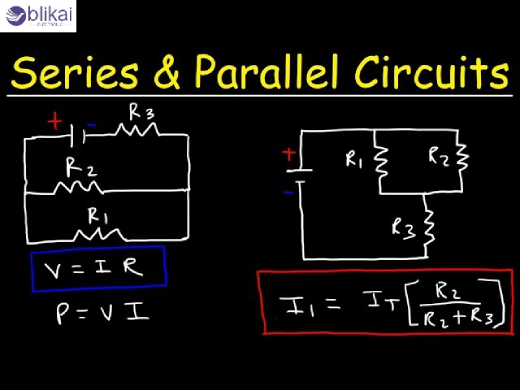
In a series circuit, the current across all the resistors is equal, but the voltage across the resistors varies with the values of the resistors.
How to Calculate Total Resistance in Series
The total resistance of series resistors is the sum of all individual resistances:
𝑅total=𝑅1+𝑅2+𝑅3+…
Example: Three resistors of 100 Ω, 200 Ω, and 300 Ω in series:
𝑅total=100+200+300=600Ω
Voltage Drop in Series Resistor Circuits
Voltage drop across each resistor is proportional to its resistance:
𝑉𝑛=𝐼×𝑅𝑛
Example: A 12 V battery connected to the three series resistors above, with current
𝐼=12/600=0.02A:
- Voltage across 100 Ω: 𝑉1=0.02×100=2.4V
- Voltage across 200 Ω: 𝑉2=0.02×200=4.0V
- Voltage across 300 Ω: 𝑉3=0.02×300=6.0V
Advantages and Disadvantages of Series Resistors
Series resistors are simple to design and provide a predictable voltage division. But when one resistor fails, the whole circuit will cease to be functional, and the reaction to the addition of more resistors rises.
Resistors in Parallel Explained
In parallel, there is a voltage across all the resistors, and the resistance of a branch causes the distribution of current.
How Current and Voltage Behave in Parallel Circuits
In a parallel circuit, all resistors have the same voltage, and the current is distributed on the basis of the resistance of a branch.
How to Calculate Total Resistance in Parallel
The total resistance of parallel resistors is calculated using:
1/𝑅total=1/𝑅1+1/𝑅2+1/𝑅3+…
Example: Three resistors of 100 Ω, 200 Ω, and 300 Ω in parallel:
1/𝑅total=1/100+1/200+1/300=0.01833
𝑅total≈54.55Ω
Current Distribution in Parallel Resistor Circuits
Current divides according to each resistor’s value. Using Ohm’s law:
𝐼𝑛=𝑉/𝑅𝑛
Example: With a 12 V supply:
- Current through 100 Ω: 𝐼1=12/100=0.12A
- Current through 200 Ω: 𝐼2=12/200=0.06A
- Current through 300 Ω: 𝐼3=12/300=0.04A
Advantages and Disadvantages of Parallel Resistors
Parallel resistors provide lower total resistance and higher reliability. If one resistor fails, other paths maintain current flow. The problem with this is that the circuit design is more complicated and the overall current may be large in case the resistances are low.
Series vs Parallel Resistors: Key Differences
|
Feature |
Series |
Parallel |
|
Current |
Same in all resistors |
Divides across resistors |
|
Voltage |
Divides across resistors |
Same across all resistors |
|
Total Resistance |
Sum of all resistances |
Less than smallest resistor |
|
Failure Effect |
Circuit stops |
Other paths still work |
|
Typical Use |
Voltage dividers |
Current splitting, reliability |
Common Applications of Series and Parallel Resistors
Voltage Dividers
The series resistors find wide use in the design of voltage dividers in which a specified voltage is gained on a greater voltage level. This is needed to drive sensors, reference voltages in ADCs and biasing.
Current Limiting
Series resistors may be used to limit the current going through a component like an LED or a small motor, and thus protect it against overcurrents, which may damage it.
LED Circuits
Serial resistors are employed to drop any extra voltage, as well as regulate current in LED applications, and parallel resistor networks enable multiple LEDs with constant brightness to be connected.
Sensor Circuits
Circuit sensor Resistors are employed in sensor circuits to give signals a set point or voltage dividers to give accurate readings. Series-parallel combinations fine-tune resistance values for precision applications.
Load Balancing and Reliability
Parallel resistors are used to allocate the current uniformly within a circuit. In case of failure of one resistor, other paths operate, and this can be useful in power supply networks and industrial applications.
Combination Circuits (Series-Parallel Resistors)
Some circuits combine series and parallel resistors for more complex designs. Simplify these circuits by calculating series and parallel groups step by step. This method is commonly used in designing filters, amplifiers, and sensor networks.
Practical Tips for Working with Resistors
- Always check the power rating to prevent overheating.
- Use standard resistor values for easy sourcing.
- Verify resistor values using color codes or a digital meter.
- Avoid mixing series and parallel connections without proper calculation.
FAQs
Can I mix different resistor values in series or parallel?
Yes. The cumulative resistance of the whole circuit is the total resistance and each voltage is proportionately split. At the same time, the overall resistance is less than that of the smallest resistor and the current divides inversely. Mixing values enables a fine control of voltages or currents, but totals are always recalculated.
What happens if one resistor fails in a series circuit?
This circuit cannot be in operation because current flow is interrupted. This can affect LEDs, sensors or voltage dividers and thus series circuits should be critically designed or redundant in critical circuits.
What happens if one resistor fails in a parallel circuit?
The other resistors are also conducting hence the circuit is still operational. The overall current is reduced, and the parallel circuit is therefore more reliable in power distribution or a sensor network.
Are series or parallel circuits safer?
Parallel circuits tend to be more dependable, as the failure of one does not terminate the circuit. The series circuits are advantageous in so much that they guard the downstream devices, but, on the other hand, they do not work when a single resistor opens.
How do I choose between series and parallel resistors?
Use series for voltage division and simple circuits, parallel for lower resistance, higher current, or redundancy. Often, a combination provides precise resistance and optimal performance.
Conclusion
Knowing the resistors in series and parallel with any electronic project is very important. The flow of the current is controlled by parallel resistors and voltage is controlled by series resistors. Mastering these concepts allows you to design circuits efficiently, choose proper resistor values, and troubleshoot electronics with confidence.
Some images are sourced online. Please contact us for removal if any copyright concerns arise.


