


Thyristor Explained: Working Principle & Applications
What Is a Thyristor?
A thyristor is a four-layer PNPN semiconductor switching device that is used to regulate electrical power by operating as a bistable switch between blocking and conduction states. The device is nonconductive until a small gate signal triggers the device, after which it admits a large current through the anode and cathode terminals. Due to this characteristic, thyristors are commonly found in controlled rectifiers, voltage regulators and power switching circuits where demand requires great accuracy in the control of electrical energy.
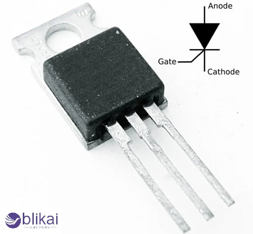
Thyristor Symbol and Terminals
A thyristor can be said to consist of three important terminals, which are known as anode, cathode and gate, which fulfill various functions in the functioning of a circuit. The anode and cathode are connected respectively to the positive supply and return path, and the gate is connected to a triggering pulse, which triggers the conduction. The circuit symbol is a diode with one extra gate terminal, and it is a graphical representation of the switching-controlled ability.
Thyristor vs Other Switching Devices
Thyristors are not designed to operate at high switching rates, as transistors and MOSFETs are, but to operate at high power. Whereas transistors must be kept active by continuous control, a thyristor snaps on once it has been triggered and keeps on conducting until the current decreases below a certain minimum; it will be more efficient with AC power control and with high electrical loads.
Internal Structure of a Thyristor
The internal construction of a thyristor consists of four alternating semiconductor layers forming three PN junctions that determine the device’s electrical behavior. These layers create interacting charge carrier regions that allow the device to switch rapidly from a high-resistance blocking state to a low-resistance conducting state when triggered. The multilayer structure enables high voltage blocking capability while maintaining efficient conduction once activated.
PNPN Layer Construction
The PNPN structure forms junctions labeled J1, J2, and J3, where the outer junctions are forward biased during normal operation and the central junction controls switching action. When forward voltage is applied without gate triggering, the middle junction prevents current flow, keeping the device in its blocking state until sufficient triggering conditions are met.
Two-Transistor Analogy Model
The operation of a thyristor is often explained using an equivalent model consisting of interconnected PNP and NPN transistors that provide regenerative feedback. When gate current initiates conduction, each transistor amplifies the other’s current, producing a positive feedback loop that rapidly drives the device into full conduction and maintains the on-state even after the gate signal is removed.
Thyristor Working Principle
A thyristor's working principle is a controlled switching by regenerative feedback in the semiconductor layers in the device, which permits the device to act as an electrically controlled latch. At the start-up, the current at the device is blocked, regardless of the forward voltage, but when a gate pulse is injected into the structure, internal amplification induces the conduction to grow exponentially until the device levels off.
Forward Blocking Mode
In forward blocking mode, the anode is positive relative to the cathode, but current flow remains minimal because the central junction is reverse-biased. The device behaves similarly to an open switch, allowing only leakage current until triggering occurs.
Triggering Process
When a gate current is applied, charge carriers are introduced into the device, reducing the barrier at the central junction and initiating conduction. Once internal current gain exceeds unity due to regenerative action, the thyristor switches abruptly into its conducting state.
Conduction Mode
Throughout the conduction mode, the thyristor has a very low voltage drop across the anode and cathode, and that will allow it to conduct large amounts of current with minimal power loss. The device will not become disconnected when the gate signal is removed, as long as the load current remains higher than the holding current level.
Turn-Off Process (Commutation)
Turning off a thyristor requires reducing the anode current below the holding current, which can occur naturally in AC circuits when current crosses zero or through forced commutation techniques using auxiliary circuitry in DC systems.
V-I Characteristics of a Thyristor
The voltage-current characteristic of a thyristor depicts three key operating regions together with reverse blocking, forward blocking, and forward conduction. Some of the key parameters also indicated on the curve are the breakover voltage, latching current, and holding current that determine the switching thresholds and stability during operation in different electrical conditions.
Types of Thyristors
Different thyristor variants have been developed to suit specific applications ranging from simple rectification to bidirectional AC control. The silicon controlled rectifier is the most common type used for controlled DC output, while TRIAC devices enable bidirectional current flow in AC circuits, and DIAC devices assist triggering functions. In high-power industrial applications, more sophisticated devices are available to enhance control and switching in high-power systems, like gate turn-off thyristors and integrated gate-commutated thyristors.
Thyristor Triggering Methods
There are many methods of triggering thyristors based on the needs of the circuit and the conditions of the environment. The most common is the gate triggering since it provides good control, whereas the voltage triggering, thermal triggering, optical triggering, and dv/dt triggering are under certain electrical or physical conditions that can shape the junction behavior and switching reliability.
Key Electrical Characteristics and Specifications
Notable thyristor requirements are the maximum repetitive voltage, the average current rating, the surge current capacity, the gate trigger current, and the switching speed, all of which define the device's appropriateness to the specific application. The nature of thermal resistance and power dissipation should also be taken into consideration to allow the reliable work of the equipment during high load conditions in the long term.
Common Thyristor Applications
Thyristors are widely applied in AC power control systems to dim lights and regulate heaters since they can provide control of the phase-angle of voltage to loads. They are also widely applied in motor speed controllers, controlled rectifiers, inverter systems, battery chargers, and industrial automation equipment, where efficient power regulation is essential.
Advantages and Disadvantages of Thyristors
The primary advantages of thyristors include high voltage handling capability, excellent efficiency under heavy loads, rugged construction, and low conduction losses, making them ideal for power electronics applications. They have some drawbacks, however, including a relatively slow switching speed, and the inability to turn off using a gate control, and are prone to triggering by dv/dt; thus, they are not as good at high-frequency switching as the modern MOSFET and IGBT devices.
Thyristor vs TRIAC vs MOSFET
Although many types of thyristors are available, a thyristor is usually chosen when high power and unidirectional control are required, a TRIAC when bidirectional AC switching is needed in consumer electronics, and a MOSFET when very high frequency operation and low V / S switching are called upon. The choice of the device varies according to the switching speed, power level, efficiency requirements and the complexity of the circuit.
Practical Design Considerations
Engineers have to take into account the heat dissipation, adequate design of gate drive, snubber networks to eliminate voltage spikes, and electromagnetic interference control when developing the circuit with thyristors to ensure stability in switching between the two states. Sufficient heat sinking and working within the safe operating range are prerequisites to the prevention of thermal runaway and the prolongation of device life.
How to Test a Thyristor
A thyristor is normally tested with a multimeter to determine the behavior of the junctions and the behavior of the trigger response by measuring conduction between the anode and cathode when a gate signal has been applied. Faulty devices often show permanent short circuits or an inability to latch, indicating internal junction damage or degradation.
Future Trends of Thyristor Technology
Even with more recent semiconductor technologies, thyristors are still needed in high-power (ultra-high-power) applications, including the HVDC transmission system, industrial drives, and renewable energy conversion systems. The modern smart power electronics are enhancing efficiency, reliability, and integration because of the changes in materials and control of gates.
Conclusion
This continues to make the thyristor an important element in power electronics because it is able to handle large quantities of electrical power with simple triggering features and with great efficiency. Knowledge in its working principle, nature and uses enables the engineers and electronics hobbyists to develop effective systems of power control that remain instrumental in industrial and energy infrastructures all over the globe.
FAQ
What makes a thyristor different from a diode?
A thyristor includes a gate terminal for controlled switching, while a diode conducts automatically when forward-biased without external control.
What causes accidental thyristor triggering?
Rapid voltage changes, electrical noise, or high temperature can unintentionally trigger a thyristor without proper protection circuits.
Some images are sourced online. Please contact us for removal if any copyright concerns arise.


