


2P4M Silicon Controlled Rectifier (SCR): Pinout and Application
The 2P4M SCR (Silicon Controlled Rectifier) is an electronic component composed of four layers arranged in a PNPN structure with three terminals. Primarily used for regulating AC current, it operates unidirectionally, permitting current flow in only one direction. Widely applied in power converters, regulators, rectifiers, and switching systems, these devices boast resilience against high currents and voltages.
Developed in 1957 by Gordon Hall and Frank W. Bill Gutzwiller at Bell Laboratories, the SCR has since found extensive use in power control scenarios. This text offers a concise overview of the pin configuration, specifications, and circuit diagrams pertinent to the 2P4M SCR, a variant frequently utilized across diverse switching and power management applications.
What is 2P4M SCR?
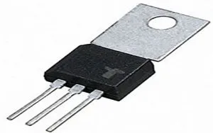
The 2P4M SCR, or Silicon Controlled Rectifier, is a semiconductor component engineered with a high-sensitivity trigger level, tailored for specialized applications requiring minimal gate currents. It falls within the SCR (Silicon Controlled Rectifier) or Thyristor family, operating as a solid-state semiconductor device. Below is an illustration depicting the fundamental structure of the 2P4M SCR device.
This rectifier finds utility across a spectrum of electronic applications characterized by low gate currents. For instance, the 2P4M SCR device serves in functions such as capacitive discharge ignition, motor control within kitchen appliances, and safeguarding against high/over-voltages in low-power supply circuits. Specifically tailored for AC rectification with low voltage and RMS voltage control scenarios, this variant of SCR is adept at handling diverse operational demands.
Terminal Arrangement/Terminal Diagram
This semiconductor device features three terminals: Anode, Cathode, and Gate. The pin configuration/diagram for the 2P4M SCR is depicted in the accompanying figure.
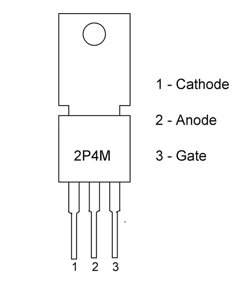
2P4M SCR Pinout
Pin Assignment:
Pin 1: Cathode Terminal - Linked to the neutral point, serving as a common connection for both input and output, and grounded.
Pin 2: Anode Terminal - Connected to the load to acquire the output, also identified as the output terminal.
Pin 3: Gate Terminal - Initiates the activation of the 2P4M SCR; applying a low-voltage trigger pulse to this terminal enables the SCR to switch ON. It regulates the input supplied to the SCR.
2P4M SCR Features
The specifications or attributes of the 2P4M SCR, as outlined in the datasheet, include:
1. Simplified circuit integration facilitated by its slender electrodes and compact dimensions.
2. Housed in a TO-202AA package type, ensuring compatibility across various setups.
3. Economical pricing makes it accessible for diverse applications.
4. Minimal holding distribution current enables flexible application design.
5. Peak reverse blocking voltage stands at 500 Volts.
6. Gate terminal peak current rating is 0.2 Amps.
7. On-State current peak reaches 2 Amps.
8. Reverse gate voltage peak is rated at 6 Volts.
9. Activation via gate voltage requires a trigger threshold of 0.8 Volts.
10. Non-repetitive surge peak On-State current peaks at 20 Amps.
11. Junction operating temperature spans from -40°C to +120°C.
12. Storage temperature range extends from -55°C to +150°C.
Schematic Overview/Utilization Guidelines
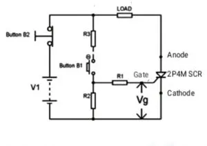
For insights into operation and practical application of the 2P4M SCR component, let's delve into a switching device example elucidated within this section. Below, you'll find an illustration detailing a straightforward circuit diagram employing the 2P4M SCR. The components essential for constructing this device's application circuit include: 2P4M SCR, two buttons, resistors, and a voltage source.
In the depicted circuit diagram, the DC voltage source is denoted by V1.
The gate voltage, serving as the trigger voltage, is applied to the gate terminal of the device.
The load resistor is connected in series with the SCR.
Upon pressing button B2, it defaults to the closed position, interrupting the circuit.
The anode terminal of the SCR is linked to the load.
The cathode terminal of the SCR connects to the opposite end of the power source.
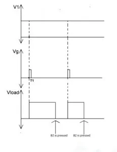
Initially, with button B1 unpressed, the SCR remains non-conductive due to the absence of gate voltage. Consequently, the device experiences the full voltage drop, resulting in a load voltage of 0V (Vload=0V), as depicted in the provided graph. This state persists until a voltage pulse is applied to the gate, achievable only when button B1 is pressed.
Now, at time T1, button B1 is pressed, causing the 2P4M SCR to conduct, leading to the appearance of the total voltage across the load, as illustrated in the accompanying graph. With the SCR triggered ON by the DC power supply, it remains in a conducting state even after the removal of gate voltage, sustaining conduction autonomously.
To return the 2P4M SCR to a high-resistance state, it is necessary to cease current flow through the device, ideally reaching a state of '0' current or cutoff. At this juncture, the stored charge within the device dissipates, enabling it to revert to its initial forward blocking state.
Achieving '0' current flow involves pressing button B2, effectively breaking the circuit loop. A single press of button B2 interrupts the circuit, reducing the current flowing through the device to '0'. Consequently, the voltage across the load drops to '0' as well, initiating the device's recovery process, as illustrated in the provided graph. This phenomenon arises from the breakdown of the circuit loop upon pressing B2.
Waveform Representation
Upon releasing button B2, the device assumes a state of forward DC voltage blockage, poised for the next trigger voltage or gate pulse. Until button B2 is pressed again, the load voltage remains at '0'. The graph provided illustrates the load voltage subsequent to the first and second trigger pulses, depicting the recurring cycle of triggering and interruption.
This operational sequence serves as an illustrative example of utilizing the 2P4M SCR as a switching device, a paradigm readily applicable across various contexts and applications.
In the preceding section, we explored the practical application of the 2P4M SCR within a small-scale circuit. Now, let's delve into its diverse utility across various domains. The applications of the 2P4M SCR encompass:
- Dimming of lights
- Charging batteries
- Regulating motors
- Ignition systems employing capacitor discharge
- Various temperature-controlled apparatuses
- AC rectification
- Switching RMS voltages
- Industrial switching tasks
- Power conversion processes
- Electric blanket functionality
- Electronic jar operation
- Electric sewing machine control
- Illumination systems
- Automatic gas lighters
As for alternative options to the 2P4M SCR, alternatives such as SN102, BT169, TIC206D, TYN604, 2N1595, and 2N1596 serve as viable substitutes.
In summary
This article provides an overview of the 2P4M SCR, a member of the SCR or thyristor family, covering its definition, pin configuration, technical specifications, circuit application, and diverse usage scenarios. As a versatile SCR model, the 2P4M variant is widely employed in power control applications, utilizing a diffusion plastic model with a p-gate design.
Now, onto your question: "What are the disadvantages of Silicon Controlled Rectifier or Thyristor?"


