


AMS1117 Voltage Regulator: Pinout, Specs & Applications Guide
What Is the AMS1117 Voltage Regulator?
The AMS1117 is a low-dropout linear voltage regulator designed to maintain a constant output voltage despite variations in input voltage or load current. The AMS1117 offers linear regulation, unlike switching regulators, which use high-frequency switching devices and thus dissipate the excess voltage as heat and operate a clean and low-noise output at all times. The device is available in a number of fixed outputs (1.8 V, 2.5 V, 3.3 V and 5 V) and also in a variable version where the designer can regulate the voltages of the outputs with external resistors.
AMS1117 Pinout Configuration
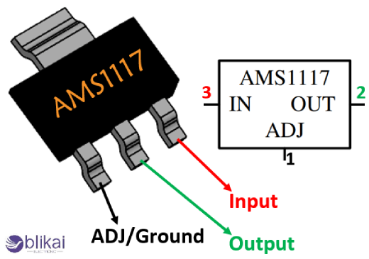
The AMS1117 has a straightforward three-pin design, which makes it easy to integrate into electronic circuits and into the layout of a printed circuit board. Each of the terminals is of significant importance, even with the number of pins being minimal, because it provides maintenance of the voltage and stable functioning in different loads.
AMS1117 Pin Functions
The AMS1117 has three pins that consist of the input pin (VIN), the ground or adjust pin (GND/ADJ), and the output pin (VOUT). The VIN pin receives the unregulated input voltage, which must be higher than the desired output voltage by at least the dropout voltage margin. The GND pin serves as the reference ground in fixed-voltage versions, while in adjustable variants it acts as the feedback node connected to a resistor divider network. VOUT pin supplies the load with the regulated voltage and provides stability due to the internal control in the form of feedback, which constantly checks the state of the output.
Package Types and Physical Layout
The AMS1117 is most commonly available in the SOT-223 surface-mount package, which provides a balance between compact size and thermal dissipation capability. The latter are also found in variants of TO-252 or other packages based on the specifications of a manufacturer. The giant metal tab is internally connected to the output or the ground and is useful in heat dissipation when soldered to a PCB copper area, and hence the board layout and thermal design are critical to consider to achieve a reliable performance.
AMS1117 Specifications and Electrical Characteristics
To select optimal operating conditions and know how to ensure the long-term reliability of the circuit, it is required that the electrical specifications of the AMS1117 should be known. Key parameters define voltage limits, current capacity, and overall efficiency characteristics.
Input Voltage Range
The input voltage that the AMS1117 usually accommodates is approximately 15V, but in practice, much lower voltages are used to reduce heat dissipation. The input voltage has to be high enough relative to the output voltage so that the designers can keep the system regulated, and yet not too much power will be wasted.
Output Voltage Options
Fixed-output versions of the AMS1117 are factory-calibrated for common logic voltages, including 1.8V, 2.5V, 3.3V, and 5V, allowing quick implementation without external resistor calculations. The adjustable model offers flexibility with the help of a resistor divider to specify the output voltage to allow custom power supply options for specialized electronic systems.
Dropout Voltage
The voltage difference necessary to allow the input and output voltages to be properly regulated is called dropout voltage, and is usually between 1.1 V and 1.3 V with a current load. This comparatively low dropout value permits the AMS1117 to be utilized in low-voltage applications more effectively than the older regulators of linear type.
Output Current Capability
The AMS1117 can deliver up to approximately 1A of output current under ideal thermal conditions, but the actual usable current depends heavily on heat dissipation and PCB design. Without adequate cooling, thermal limitations may significantly reduce continuous current capability.
Thermal and Protection Features
The AMS1117 has inherent protection measures, which are thermal shutdown and internal current limiting, in order to avoid any harm. These safety features automatically reduce output or turn off operation when temperature or current exceeds safe operating limits, improving reliability in real-world applications.
How the AMS1117 Works
The AMS1117 works on a linear regulation design, which measures the output voltage with a reference voltage inside the chip by using a feedback amplifier. As a result of decreased output voltage caused by high load demand, the internal pass transistor modulates conduction in a bid to normalize the proper voltage level. Conversely, the output voltage increases, thus decreasing conduction to stabilize the situation. This is an analog constant control loop, thus providing smooth regulation of voltages with a very low level of noise on the output and makes this device especially handy in a sensitive analog and digital circuit where switch noise would be unacceptable.
Typical AMS1117 Application Circuits
The AMS1117 can be employed in very diverse power regulation applications throughout the design of electronics because of its versatility.
5V to 3.3V Power Conversion
One of the most common applications involves converting a 5V supply from USB or adapters into a stable 3.3V output required by microcontrollers, sensors, Wi-Fi modules, and logic ICs. This configuration is widely used in Arduino-compatible boards and IoT development platforms.
Adjustable Voltage Regulator Circuit
In adjustable designs, the voltage divider is made up of two resistors that are able to be connected between the output and adjust pin; the designers are able to set the exact voltage that is needed, depending on the needs of the system, whilst keeping a stable regulation.
Power Supply Filtering and Capacitor Selection
The stable operation of AMS1117 requires input and output capacitors to minimize the ripple of the voltage and eliminate the oscillations in the feedback circuit. Typical designs use electrolytic or tantalum capacitors with appropriate capacitance and equivalent series resistance (ESR) values to ensure regulator stability.
AMS1117 vs Other Voltage Regulators
Choosing the correct regulator often involves comparing performance characteristics with alternative devices.
AMS1117 vs LM1117
The AMS1117 and LM1117 have much in common with regard to electrical properties and pin compatibility; however, there may be variations in the manufacturing tolerances, thermal, and brand-related reliability, so designers need datasheets to replace components.
AMS1117 vs Switching Regulators
The AMS1117 is easier to design into an application and has reduced electrical noise, but is much less efficient than switching regulators, particularly when there is a large voltage difference between input and output, and thus generates higher levels of heat.
Advantages and Disadvantages of the AMS1117
The AMS1117 has such benefits as low cost, easy to use, few external components and clean output voltage, which can be used in both analog and RF circuits. However, its linear operation results in reduced efficiency and higher thermal losses compared with modern switching converters, making it less suitable for battery-powered or high-power applications where energy efficiency is critical.
Common Applications of the AMS1117
The AMS1117 has applications in Arduino boards, ESP8266 and ESP32 modules, sensor interfaces, communication, power modules, USB-powered electronics, and embedded control systems. This has made it popular because of its dependability and capability to generate regulated voltages used in digital electronics in very little time.
Design Tips for Using the AMS1117
Successful AMS1117 implementation requires careful attention to thermal management, adequate copper area for heat dissipation, proper capacitor placement close to pins, and ensuring sufficient input voltage headroom above dropout limits. Calculations of the power dissipation should also be taken into consideration by the designers in order to avoid overheating when operating heavy loads.
Common Problems and Troubleshooting
The problems that are common with the AMS1117 are: overheating under the condition of high differences of input voltage, erratic output and voltage drop under the condition of inadequate input. These problems are normally addressed by proper circuit design, the correct component values, and thermal considerations.
FAQ
Why does the AMS1117 get hot?
The heat is caused by dissipation of excess voltage as power loss in the linear regulator, particularly when delivering high current or when large input-to-output voltage differences are present.
Can AMS1117 power Arduino or ESP modules?
Yes, the AMS1117 is commonly used to supply 3.3V power for Arduino-compatible boards and ESP modules, provided thermal limits and current requirements are respected.
Conclusion
The AMS1117 voltage regulator has continued to be a very convenient and easily available device to create stable low-voltage power rails within electronic circuits. Ease of use in the pin setup, wide accessibility, as well as its reliability in consumer electronics, embedded systems and prototyping, make it a relatively suitable component. Though it is less efficient in switching regulators, its low noise output and simple application remain a favorite with engineers in need of a sure linear voltage regulator in simple designs.
Some images are sourced online. Please contact us for removal if any copyright concerns arise.


