


Basic Knowledge of Electronic Parts:Complete Guide
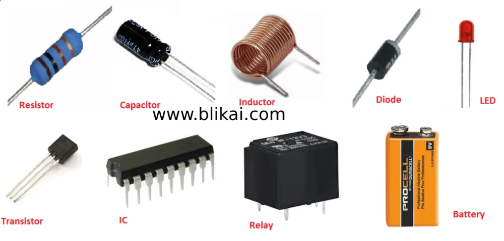
This article will introduce key components of electronic components, including resistors, capacitors, diodes, voltage regulators, varactor diodes, and transistors, along with relevant knowledge about field-effect transistor amplifiers.Let's begain!
What is resistance?
Resistance, in simple terms, refers to the opposition encountered by an electric current in a circuit, or it can be seen as the impediment offered by a material to the flow of current. The greater the resistance, the more opposition the current faces, resulting in a smaller current. Conversely, the smaller the resistance, the less opposition the current encounters, resulting in a larger current.
The symbol for resistance is "R". The unit of resistance is the ohm, symbolized by the Greek letter "Ω".
The Function of Resistance
In circuits, resistance is represented by "R" followed by a number, for example, R1 denotes resistor number 1. The primary functions of resistance in circuits include current division, current limiting, voltage division, and biasing.
Parameter Identification: The unit of resistance is the ohm (Ω), with multiplier units such as kiloohm (KΩ) and megaohm (MΩ). The conversion method is: 1 megaohm = 1000 kiloohms = 1000000 ohms. Resistance parameters are labeled using three methods: direct marking, color code, and numerical code.
a. The numerical code method is mainly used for small-sized circuits like SMDs (surface-mount devices). For example, 472 represents 47 × 100Ω (i.e., 4.7K); 104 represents 100K.
b. The color ring notation method is the most commonly used. An example is provided below:
Four-band resistor Five-band resistor (precision resistor)
The relationship between the color bands on a resistor and their respective values and multipliers is shown in the table below:
- Color Significant Digit Multiplier Tolerance (%)
- Silver / x0.01 ±10
- Gold / x0.1 ±5
- Black 0 +0 /
- Brown 1 x10 ±1
- Red 2 x100 ±2
- Orange 3 x1000 /
- Yellow 4 x10000 /
- Green 5 x100000 ±0.5
- Blue 6 x1000000 ±0.2
- Violet 7 x10000000 ±0.1
- Grey / x100000000 /
- White 9 x1000000000 /
What is Capacitor?
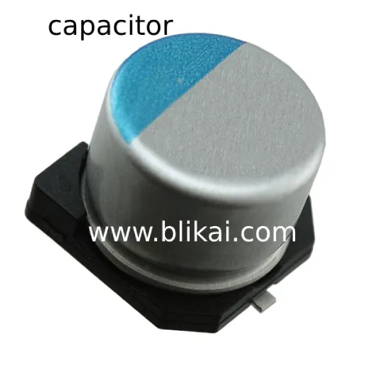
In circuits, capacitors are typically represented by "C" followed by a number (e.g., C13 denotes capacitor number 13). A capacitor is a component composed of two metal foils separated by an insulating material. The primary characteristic of capacitors is to block direct current while allowing alternating current to pass through.
The Capacitor's Role
The magnitude of a capacitor's capacitance represents its ability to store electrical energy. The impedance offered by a capacitor to an alternating current signal is known as capacitive reactance (XC), which is dependent on the frequency of the AC signal and the capacitance. The formula for capacitive reactance is XC = 1 / (2πfC), where f represents the frequency of the AC signal, and C represents the capacitance.
Common types of capacitors used in telephony include electrolytic capacitors, ceramic capacitors, surface-mount capacitors, monolithic capacitors, tantalum capacitors, and polyester capacitors.
Identification Methods: The methods for identifying capacitors are similar to those for resistors and include direct marking, color coding, and numerical coding. The basic unit of capacitance is the farad (F), with other units such as millifarad (mF), microfarad (uF), nanofarad (nF), and picofarad (pF). The conversion factors are: 1 farad = 10^3 millifarads = 10^6 microfarads = 10^9 nanofarads = 10^12 picofarads.
For capacitors with large capacitance values, the capacitance is directly marked on the capacitor, such as 10uF/16V.
For capacitors with small capacitance values, the capacitance is represented either by letters or numbers.
Letter representation: 1m = 1000uF, 1P2 = 1.2pF, 1n = 1000pF.
Number representation: Generally represented by a three-digit number, where the first two digits indicate the significant figures and the third digit indicates the multiplier. For example, 102 represents 10 x 10^2 pF = 1000pF, and 224 represents 22 x 10^4 pF = 0.22uF.
Capacitance Tolerance Table
Symbol F G J K L M
Tolerance ±1% ±2% ±5% ±10% ±15% ±20%
For example, a ceramic capacitor marked as 104J indicates a capacitance of 0.1uF with a tolerance of ±5%.
What is a diode?
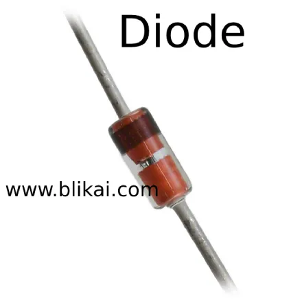
A diode often represented in circuits by "D" followed by a number (e.g., D5 denotes diode number 5), is a semiconductor device with two terminals, typically allowing current to flow in one direction only.
The Function of Diodes
The primary characteristic of a diode is its unidirectional conductivity. That is, under forward bias (positive voltage), the diode exhibits low resistance and allows current to flow freely, whereas under reverse bias (negative voltage), the diode has a very high or infinite resistance, effectively blocking current flow.
Due to these characteristics, diodes find application in various circuit functions such as rectification, isolation, voltage regulation, polarity protection, encoding control, frequency modulation, and noise reduction in telecommunication devices. Diodes used in telephony include rectifier diodes (e.g., 1N4004), isolation diodes (e.g., 1N4148), Schottky diodes (e.g., BAT85), light-emitting diodes (LEDs), and voltage regulator diodes.
Identification of Diodes
Diode identification is relatively straightforward. The cathode (negative terminal) of small signal diodes is often marked with a colored band on the diode's body. Some diodes use specific symbols to indicate the cathode (negative) or anode (positive) terminals, while others may use "P" and "N" symbols. For light-emitting diodes, the positive and negative terminals can be identified by their pin lengths, with the longer pin being positive and the shorter one negative.
Testing Precautions
When testing a diode with a digital multimeter, the red probe should be connected to the diode's anode (positive) and the black probe to the diode's cathode (negative). This setup allows for the measurement of the forward voltage drop, which indicates the diode's conductivity. This is opposite to the connection used with an analog multimeter.
Commonly Used 1N4000 Series Diodes Voltage Ratings:
Model 1N4001 1N4002 1N4003 1N4004 1N4005 1N4006 1N4007
Voltage (V) 50 100 200 400 600 800 1000
Current (A) 1 1 1 1 1 1 1
What is a voltage regulator diode?
A voltage regulator diode, often represented in circuits by "ZD" followed by a number (e.g., ZD5 denotes voltage regulator diode number 5), is a type of semiconductor diode designed to maintain a constant voltage across its terminals after it enters the breakdown region.
Principle of Voltage Regulation in Voltage Regulator Diodes
The characteristic feature of a voltage regulator diode is that once it enters the breakdown region, the voltage across its terminals remains essentially constant. Therefore, when a voltage regulator diode is connected in a circuit, if there are fluctuations in the power supply voltage or variations in the voltages at different points in the circuit due to other reasons, the voltage across the load will remain stable.
Fault Characteristics
Faults in voltage regulator diodes mainly manifest as open circuits, short circuits, and unstable voltage regulation values. Among these three types of faults, the former results in an increase in the power supply voltage, while the latter two lead to a decrease in the power supply voltage to zero or unstable output.
Commonly Used Voltage Regulator Diode Models and Voltage Values:
Model 1N4728 1N4729 1N4730 1N4732 1N4733 1N4734 1N4735 1N4744 1N4750 1N4751 1N4761
Voltage (V) 3.3V 3.6V 3.9V 4.7V 5.1V 5.6V 6.2V 15V 27V 30V 75V
What is an inductor?
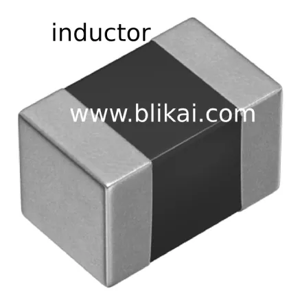
An inductor, often represented in circuits by "L" followed by a number (e.g., L6 denotes inductor number 6), is a passive electronic component that stores energy in the form of a magnetic field when electric current flows through it.
An inductor coil is typically made by winding an insulated wire around an insulated core or frame a certain number of times. When a direct current (DC) flows through an inductor, the DC resistance is minimal, mainly due to the resistance of the wire itself, resulting in a very small voltage drop. However, when an alternating current (AC) signal passes through an inductor, the coil generates a self-induced electromotive force (EMF), also known as back electromotive force (back EMF), in the opposite direction to the applied voltage. This back EMF opposes the flow of AC, causing the inductor's impedance to increase with higher frequencies. Hence, the primary characteristic of an inductor is that it allows DC to pass through while resisting AC, with the impedance increasing with higher frequencies.
Inductors can be used in circuits with capacitors to form oscillating circuits or in filters to block certain frequencies.
Inductors are typically identified using direct marking or color coding, similar to resistors. For example, a brown-black-gold-gold color code indicates a 1μH inductor with a 5% tolerance.
The basic unit of inductance is the henry (H). Other commonly used units include millihenry (mH) and microhenry (μH). The conversion factors are: 1H = 10^3mH = 10^6μH.
What is a varactor diode?
A varactor diode, also known as a variable capacitance diode or varicap diode, is a specialized type of diode designed based on the principle that the junction capacitance of a regular diode, known as the "PN junction," can vary with the applied reverse voltage. Varactor diodes are specifically designed to exploit this characteristic.
Varactor diodes are commonly used in high-frequency modulation circuits, particularly in mobile phones or landline telephones, to modulate low-frequency signals onto high-frequency carriers for transmission. In operation, the modulation voltage is typically applied to the varactor diode's cathode, causing the internal junction capacitance to vary with changes in the modulation voltage.
When a varactor diode fails, it may exhibit leakage or deteriorated performance:
Leakage current: If leakage occurs, the high-frequency modulation circuit may not function properly, or the modulation performance may degrade.
Deteriorated performance: If the varactor's performance deteriorates, the high-frequency modulation circuit may operate unstably, leading to distorted high-frequency signals being transmitted and received by the recipient.
In the event of either of these conditions, it is advisable to replace the varactor diode with the same model to restore proper functionality.
What is a bipolar junction transistor (BJT)?
A bipolar junction transistor (BJT), commonly denoted in circuits by "Q" followed by a number (e.g., Q17 denotes transistor number 17), is a special semiconductor device containing two PN junctions and possessing amplification capabilities.
Characteristics:
BJTs come in two types: NPN and PNP. These types complement each other in terms of operational characteristics. Transistors of these two types are often paired in complementary configurations in circuits such as OTL (output transformerless) circuits. Common PNP transistors used in telephony include A92 and 9015, while common NPN transistors include A42, 9014, 9018, 9013, and 9012.
BJTs are primarily used for amplification in electronic circuits and can be configured in three common arrangements:
Common emitter configuration: Provides medium input impedance, medium output impedance, high voltage gain, high current gain, and high power gain. It is typically used as an intermediate stage in multistage amplifiers or for low-frequency amplification.
Common collector configuration (also known as the emitter follower or grounded collector configuration): Offers high input impedance, low output impedance, low voltage gain (close to unity), high current gain, and low power gain. It is commonly used as input or output stages or for impedance matching.
Common base configuration: Features low input impedance, high output impedance, high voltage gain, low current gain (close to unity), and medium power gain. It finds applications in high-frequency or wide-band circuits and constant current source circuits.
The table below summarizes the characteristics and applications of the three BJT configurations:
What is a field-effect transistor (FET) amplifier?
_amplifier.webp)
Field-effect transistors (FETs) have advantages such as high input impedance and low noise, making them widely used in various electronic devices. Particularly, using FETs as the input stage of electronic devices can achieve performance that is difficult to attain with conventional transistors.
There are two main types of FETs: junction-type (JFET) and insulated-gate type (IGFET, including MOSFETs). Both types operate on the same control principle.
Comparison between FETs and transistors:
FETs are voltage-controlled devices, whereas transistors are current-controlled devices. FETs are preferred when only a small amount of current can be drawn from the signal source. Transistors are preferable when the signal voltage is low but can allow more current to be drawn from the signal source.
FETs utilize majority carriers for conduction, hence they are termed unipolar devices, whereas transistors utilize both majority and minority carriers for conduction, hence they are termed bipolar devices.
Some FETs allow for interchangeability of the source and drain terminals, and the gate voltage can be positive or negative, providing greater flexibility compared to transistors.
FETs can operate at very low currents and voltages. Moreover, their manufacturing process allows for easy integration of multiple FETs on a single silicon wafer, making them widely used in large-scale integrated circuits.
In summary, FETs are voltage-controlled devices with high input impedance, making them suitable for applications requiring low current and low voltage operation, as well as for integration into integrated circuits.
About Blikai Mall
Blikai Mall (WWW.Blikai.COM) was founded in 2023, committed to providing customers with comprehensive online purchasing services for electronic components, leading the nation in transaction volume. With a modern electronic component warehouse of over 10,000 square meters, our on-hand inventory exceeds 100,000 varieties. Our group's self-operated services in the electronic industry chain include: online EDA (LCEDA), industry-leading PCB prototyping/small-batch production, component mall, stencil manufacturing, SMT assembly, as well as electronic design education and solutions. As a vertically integrated mall for electronic components with a complete variety, self-operated inventory, and guaranteed quality, all components at Blikai Mall are purchased from original manufacturers or authorized distributors through legitimate channels, ensuring genuine products. We provide professional one-stop component procurement services for you.


