


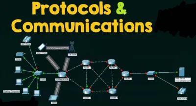
Communication Protocols: Overview,Working Principle and Applications
In the digital realm, communication protocols set various rules. For instance, on the Internet, these protocols are created by organizations like the World Wide Web Consortium (W3C) and the Internet Engineering Task Force (IETF). These bodies ensure global functionality and address multiple risks and vulnerabilities within these technologies. Communication protocols are essential when HTTP upgrades to HTTPS, making the widespread use of SSL (Secure Sockets Layer) certificates commonplace. Other protocols control data packets across global network routes, which can sometimes be as complex as particle physics. As technology progresses, new communication protocols are adopted in sophisticated networks. The Internet of Things (IoT) is poised to develop the latest communication protocols to link a vast array of devices to a universal network. This article provides an overview of communication protocols in embedded systems.
What are Communication Protocols?
The precise definitions of digital message formats and rules are known as communication protocols. These protocols primarily facilitate the exchange of messages between computer systems. They are crucial in telecommunications systems because they ensure consistent message transmission and reception. These protocols encompass error detection and correction, signaling, and authentication. They also describe semantics and syntax, and integrate analog and digital communications.
The implementation of these protocols can be achieved through both hardware and software. Communication protocols exist in thousands of types and are used extensively in both analog and digital communications, making computer networks impossible without them.
Introduction of Protocol
Protocol: A protocol is a set of rules and regulations.
Communication: Communication is the exchange of information from one system to another using a medium.
Communication Protocol: A communication protocol is a set of rules and regulations that enable two electronic devices to connect and exchange data with each other.
Why is Communication Protocol Important?
Communication protocols enable diverse network devices to interact by transmitting analog signals, digital signals, various files, and processing data from one device to another. These protocols are essential in telecommunication and computer networks, where appropriate rules are implemented to transmit information from the source to the destination. The most crucial protocols in networking are Transmission Control Protocol (TCP) and User Datagram Protocol (UDP).
Types of Communication Protocols
Communication protocols can be categorized into two types:
- Inter System Protocol
- Intra System Protocol
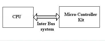
Inter System Protocol
The inter-system protocol is used to communicate between two different devices, such as a computer and a microcontroller kit. This communication occurs through an inter bus system.
The different categories of intersystem protocols mainly include the following:
- UART Protocol
- USART Protocol
- USB Protocol
UART Protocol
UART stands for Universal Asynchronous Receiver/Transmitter. The UART protocol is a serial communication protocol with two wire connections. The data cable signal lines are labeled as Rx and Tx. Serial communication is typically used for transmitting and receiving signals. Data is transferred and received serially, bit by bit, without clock pulses. The UART takes bytes of data and sends the individual bits sequentially.
UART is a half-duplex protocol, meaning it can transfer and receive data, but not simultaneously. Most controllers have a hardware UART on board. It uses a single data line for both transmitting and receiving data. The protocol consists of one start bit, 8-bit data, and one stop bit, indicating that the 8-bit data transfer changes the signal from high to low.
Examples: Emails, SMS, Walkie-talkies.
USART Protocol
USART stands for Universal Synchronous and Asynchronous Receiver/Transmitter. It is a serial communication protocol with two wire connections. The data cable signal lines are labeled as Rx and TX. This protocol is used for transmitting and receiving data byte by byte along with clock pulses. It is a full-duplex protocol, meaning it can transmit and receive data simultaneously at different baud rates. Various devices use this protocol to communicate with microcontrollers.
Example: Telecommunications.
USB Protocol
USB stands for Universal Serial Bus. It is also a serial communication protocol with two wire connections. The data cable signal lines are labeled D+ and D-. This protocol is used for communication with system peripherals. The USB protocol enables the sending and receiving of data serially between the host and peripheral devices. USB communication requires driver software based on the system's functionality. USB devices can transfer data on the bus without any request from the host computer.
Nowadays, most devices use this technique for communicating via the USB protocol. For instance, a computer can communicate with an ARM controller using USB. USB transfers data in different modes: slow speed mode (10 kbps to 100 kbps), full speed mode (500 kbps to 10 Mbps), and high-speed mode (25 Mbps to 400 Mbps). The maximum cable length for USB is 4 meters.
Examples: Mouse, Keyboard, Hubs, Switches, Pen Drives.
Differences Between the Inter System Protocols
The intersystem protocols primarily include UART, USART, and USB.
UART
UART stands for Universal Asynchronous Transmitter and Receiver. It primarily utilizes two-wire protocols for transmitting and receiving data. UART transfers data byte by byte without clock pulses. It operates in half-duplex mode and is generally slower compared to USART.
USART
USART stands for Universal Synchronous and Asynchronous Data Transmitter and Receiver. It operates as a two-wire protocol for both transmitting and receiving data. USART transfers data blocks using clock pulses. It supports full-duplex communication. However, compared to USB, USART tends to operate at slower speeds.
USB
USB stands for Universal Serial Bus. It operates as a two-wire protocol with lines labeled D+ and D-. USB transmits and receives data using clock pulses. It supports full-duplex communication and is generally faster compared to USART and UART.
Intra System Protocol
The intra-system protocol facilitates communication between two devices within the same circuit board. By employing these intra-system protocols, peripherals of the microcontroller can be expanded without the need for external protocols. However, using intra-system protocols increases circuit complexity and power consumption. On the other hand, it reduces costs and enhances data security.
Categories of Intra System Protocol
The different categories of intra-system protocols mainly include:
- I2C Protocol
- SPI Protocol
- CAN Protocol
I2C Protocol
I2C stands for Inter-Integrated Circuit, utilizing only two wires to connect all peripherals to the microcontroller. It requires the SDA (Serial Data Line) and SCL (Serial Clock Line) to transmit information between devices. I2C operates as a master-to-slave communication protocol, where each slave possesses a unique address. The master device sends the address of the target slave device and controls the read/write operations. When the address matches, the targeted slave device responds while others remain inactive.
Once communication is established between the master and the selected slave device, data transmission and reception occur. The transmitter sends 8-bit data, and the receiver responds with a 1-bit acknowledgment. After completing communication, the master device issues a stop condition. Originally developed by Philips Semiconductors, the I2C bus simplifies connections between CPUs and peripheral chips.
In embedded systems, peripheral devices often connect to the microcontroller as memory-mapped devices using I2C, requiring just two wires: SDA for data and SCL for clock. These bidirectional lines necessitate pull-up resistors to ensure proper signal operation:
I2C Pull-up Resistors
Pull-up resistors are crucial in I2C for the SCL and SDA lines due to their open-drain drivers:
Both SDA and SCL lines can drive the output low but cannot drive it high.
Pull-up resistors are necessary to allow the lines to return to the high state when no device is actively pulling them low.
SPI Protocol
SPI, or Serial Peripheral Interface, is a serial communication protocol originally developed by Motorola. It is sometimes referred to as a 4-wire protocol, utilizing four wires: MOSI, MISO, SS, and SCLK. SPI facilitates communication between master and slave devices. The master device first configures the clock frequency.
Next, the master selects a specific slave device for communication by activating the chip select signal. Communication then proceeds between the master and the selected slave device. Only one slave device can be selected at a time. SPI operates as a full-duplex communication protocol and is not limited to transferring 8-bit words.
CAN Protocol
CAN, or Controller Area Network, is a serial communication protocol requiring two wires: CAN High (H+) and CAN Low (H-). Developed by Robert Bosch GmbH in 1985, CAN was designed for in-vehicle networks. It operates based on a message-oriented transmission protocol.
Differences Between the Intra System Protocols
The intra-system protocols primarily consist of I2C, SPI, and CAN.
I2C
- I2C, which stands for Inter-Integrated Circuit, was developed by Philips.
- I2C is a half-duplex communication protocol.
- It uses two wires, SCL and SDA, for communication.
- I2C supports multi-master communication.
- It is commonly used on circuit boards for synchronization.
SPI
- SPI stands for Serial Peripheral Interface and was developed by Motorola.
- SPI is a full-duplex communication protocol.
- It uses four wires: SCLK, MISO, MOSI, and SS.
- SPI operates as a single master protocol.
- It is commonly utilized on circuit boards for synchronization.
CAN
- CAN stands for Controller Area Network and was developed by Bosch.
- CAN is a full-duplex communication protocol.
- It uses two wires: CANH+ and CANH- for communication.
- CAN supports multi-master communication.
- It is commonly used on two circuit boards for synchronization.
Communication Protocols in IoT
IoT-based devices are particularly vulnerable to threats, which can be mitigated by employing appropriate protocols. Communication protocols in IoT ensure robust security for data exchanged among connected devices.
These devices can connect via either an IP network or a non-IP network, each with differences in power consumption, range, and memory usage. IP networks offer robust connectivity but consume significant memory and power, while non-IP networks like Bluetooth require less power and memory but have limited range.
Key advantages of IoT communication protocols include high quality, reliability, interoperability, flexibility for innovation, and global scalability. These protocols are categorized into IoT network protocols and IoT data protocols.
The Top 10 IoT Communication Protocols include the following:
- WiFi
- SigFox
- Bluetooth
- LoRaWAN
- NFC (Near Field Communication)
- Z wave
- Zigbee
- OPC- UA
- Cellular
- MQTT
Data Communication Protocols
Data communication protocols play a crucial role in enabling networks, computers, or devices to communicate effectively with each other.
These protocols establish standardized rules and methods, akin to a common language, facilitating interaction between computers or networks. For example, when a user wishes to send an email to another person, they compose the email on their computer, including details, messages, and attachments.
Once the user sends the email, several actions occur immediately to ensure the recipient receives it. The message traverses the network and reaches the intended recipient. These protocols specify how the message will be formatted for transmission across the network, how the receiving computer can check for errors, and other necessary details.
PLC Communication Protocols
The primary communication protocols used for PLC and network connections are supported by various PLC software products. These protocols primarily depend on three fundamental aspects: baud rate, network length, and the number of nodes. Below is a list of PLC communication protocols:
- Profibus
- Interbus
- ControlNet
- ProfiNet
- CompoNet
- DirectNet
- Modbus
- MelsecNet
- EtherCAT
- DF-1 Protocol
- Optomux
- Host Link Protocol
- RAPIENet
- EtherNet/IP
- Mechatrolink
- PPI- Point to Point
- Ethernet Powerlink
- Multi-Point Interface (MPI)
- Data Highway (DH)
- Actuator Sensor Interface (ASI)
- DeviceNet
- Highway Addressable Remote Transducer Protocol (HART)
- Ethernet Global Data (EGD)
- Factory Interface Network Service Protocol (FINS)
- Open Smart Grid Protocol (OSGP)
- Recommended Standard (RS-232, RS-422, and RS-485) Protocols
- Bristol Standard Asynchronous Protocol (BSAP)
- Distributed Network Protocol (DNP3)
- Service Request Transport Protocol (SRTP)
- Smart Distributed System Protocol (SDS)
- Process Image Exchange Protocol (PIEP)
Characteristics of PLC Communication Protocols
Standard protocols are utilized when PLC modules connect over the network. These protocols support different speeds, distances, and the number of connected devices.
- Ethernet protocol: Baud rate is 100 Mb/s, length is a few kilometers, and supports 255 nodes.
- RS-485 protocol: Baud rate is 10 Kb/s, length is 1.2 km, and supports 32 nodes.
- Profibus protocol: Baud rate ranges from 5-12 Mb/s, length is 15 km, and supports 127 nodes.
- RS-232 protocol: Baud rate is 19.2 Kb/s, length is 10 meters, and supports 1 node.
- MPI protocol: Baud rate ranges from 19.2 to 38.4 Kb/s, length is 50 meters, and supports 32 nodes.
- PC Adapter: Baud rate is 9600 Kb/s, length is 15 meters, and supports 1 node.
- PPI protocol: Baud rate is 187.5 Kb/s, length is 500 meters, and supports 1 node.
- USB Adapter: Baud rate is 57.6 Kb/s, length is 10 meters, and supports 1 node.
- DH protocol: Baud rate is 230.4 Kb/s, length is 3.048 km, and supports 64 nodes.
- DeviceNet protocol: Baud rate is 500 Kb/s, length is 0.487 km, and supports 64 nodes.
- ControlNet protocol: Baud rate is 5 Mb/s, length is 30 km.
Communication Protocols in Cloud Computing
In cloud computing, two primary communication protocols facilitate connection and communication: MQTT and HTTP. Devices communicate through Cloud IoT Core using either HTTP or MQTT bridges, which are essential components of Cloud IoT Core. When creating a device registry, protocols such as HTTP and MQTT can be selected. MQTT, a widely used protocol, is particularly common in machine-to-machine interactions and is well-supported by embedded devices.
HTTP operates as a connectionless protocol, where devices do not maintain continuous connections to the Cloud IoT Core. Instead, they send requests and receive responses as needed. Cloud computing protocols encompass a set of rules enabling electronic elements to connect and exchange data. These protocols are pivotal for communication, storage, encryption, decryption, security, user login management, and more.
Some examples of cloud computing protocols include:
- Gossip Protocol
- MTP (Media Transfer Protocol)
- CLNP (Connection Less Network Protocol)
- CEE (Coverage Enhanced Ethernet Protocol)
- SRP (State Routing Protocol)
- SSHP (Secure Shell Protocol)
- IGMP (Internet Group Management Protocol)
This overview covers communication protocols, their types, and the distinctions between inter-system and intra-system protocols.
Related Artilces
What Arduino Mega 2560 is and How it works
What is an Induction Motor :All You Need to Know
What L298 Motor Driver IC can do and How it Works
What is an Induction Motor :All You Need to Know


