


What Retardation Test is:Everything You Need to Know
A DC machine represents an electromechanical apparatus utilized for converting DC electricity into mechanical energy or vice versa. If the DC machine transforms energy from DC electrical to mechanical, it operates as a DC motor. Conversely, if it converts energy from mechanical to DC electrical, it functions as a DC generator. Operating on the principle of electromagnetic induction, DC machines undergo various tests to evaluate their performance and efficiency. Among these tests, the retardation test stands out as one of the most crucial. The efficiency of a DC machine hinges largely on its losses; reduced losses correspond to higher machine efficiency. This article offers a succinct overview of the Retardation Test, encompassing its underlying theory and practical applications.
What is the Retardation Test?
The retardation test, also referred to as the running down test, serves as a highly efficient method for identifying the iron, friction, and windage losses present within DC machines. This test not only assesses stray or rotational losses but also evaluates efficiency across various loads.
Conducting the Retardation test involves applying a braking torque to the motor shaft and monitoring the corresponding armature voltage, speed, and current. As a result, the motor operates in reverse, generating a braking effect.
During this test, the motor's reverse operation induces a magnetic field in the opposite direction, which interacts with the stray magnetic fields within the motor. This interaction triggers the flow of eddy currents within the iron core, contributing to stray losses. By measuring the voltage and armature current during the Retardation test, it becomes possible to quantify these stray losses.
Retardation Test Operational Principle
When examining a DC shunt motor operating under no-load conditions, if the armature supply is disconnected while the field remains energized, the motor gradually decelerates until it comes to a complete halt. During this process, the kinetic energy of the armature is dissipated to overcome windage, iron, and friction losses.
Similarly, when both the armature and field excitation supplies are severed, the motor again decelerates and eventually stops. At this point, the kinetic energy of the armature is solely utilized to overcome friction and windage losses, as there is no flux present to induce iron losses.
Conducting the first test allows for the determination of windage, friction, iron losses, and efficiency of the DC machine. However, by executing the second test, it becomes possible to differentiate windage and friction losses from iron losses.
Theory of the Retardation Test
The most straightforward and effective method for assessing the efficiency of a DC machine. This approach enables the determination of both mechanical and iron losses in the DC machine. By first identifying the shunt copper and armature losses at a specific electrical load, the efficiency of the DC machine can be calculated at that load. During this test, the DC machine operates as a motor slightly above its normal speed. Subsequently, the armature supply is disconnected while the field remains energized at its normal level. As a result, the machine's speed gradually decreases below its normal value, and the time taken for this speed reduction is recorded. Through these observations, rotational losses including friction, iron, and windage losses, as well as the machine's efficiency, can be determined.
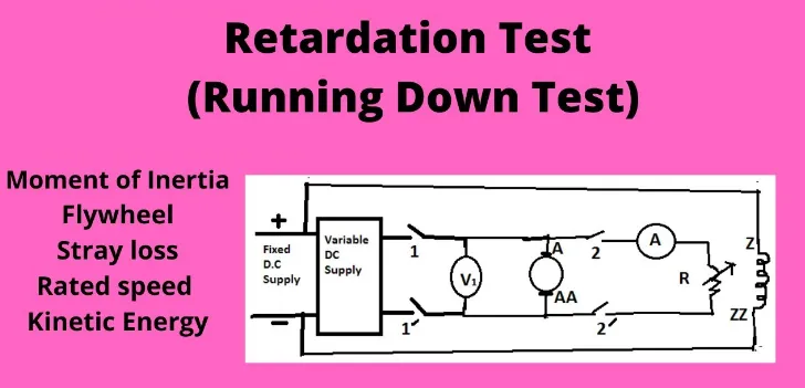
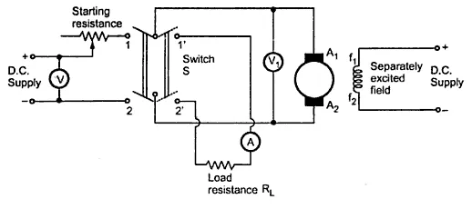
The circuit diagram for the retardation test is depicted below. This test is utilized to assess total stray losses, encompassing a combination of mechanical losses such as windage and friction, along with the iron losses of the DC machine. In this circuit, A1 and A2 represent the armature terminals. The procedure for conducting the Retardation Test on DC Machines is as follows:
Key Steps in the Retardation or Running Down Test are outlined as follows:
1. Initially, activate the DC machine in the usual manner. Then, elevate the machine's speed slightly above the designated level by adjusting its resistance.
2. Once the desired speed is attained, disengage the power supply to the armature while maintaining the field excitation at its standard level.
3. Allow sufficient time for the machine's speed to decline below the rated speed, then record the speed values in revolutions per minute (rpm) and the corresponding time in seconds using a tachometer.
4. During this process, the armature decelerates, and the kinetic energy within the armature is utilized to counteract the stray or rotational losses, including friction, winding, and iron losses.
The formula for calculating rotational losses (W) involves the armature's inertia moment (I) and the rate of change of speed (dN/dt):
W = 0.011 IN dN/dt
Determining the inertia moment (I) of the armature poses a challenge, as it cannot be directly measured or calculated. Therefore, an alternative test, such as the flywheel method, is employed to either ascertain or eliminate the 'I' value from the equation mentioned above.
Illustration:
Consider a scenario where the normal speed of the DC machine is 1200 rpm. Upon conducting the retardation test, the time required for the DC machine's speed to decrease from 1050 to 970 rpm is measured as 10 seconds, with the field excited as usual. Given an armature inertia moment of 80 kg m², the rotational losses (W) can be calculated using the formula:
W = 0.011 IN dN/dt.
With I = 80 kg m², N = 1200 rpm, dN = 1050 - 970 = 80 rpm, and dt = 10 seconds.
Thus, substituting these values into the formula:
W = 0.011 × 80 × 1200 × (80/10).
This simplifies to:
W = 0.011 × 80 × 1200 × 8 = 8448 watts.
Advantages and Disadvantage
Retardation Test Advantages:
1. The DC machine operates as a motor above its normal speed during this test.
2. It is effective in evaluating the efficiency of the DC machine.
3. This test requires significantly less power compared to running the motor and generator system at full load.
4. It is considered the simplest and most effective method for determining the efficiency of a DC machine.
5. The test facilitates the comprehensive measurement of motor losses.
6. It offers a high level of convenience and ease of execution.
Retardation Test Disadvantage:
1. The primary drawback lies in accurately determining the constantly changing speed during the test.
2. This test is applicable only to separately-excited DC machines.
Applications
The retardation test finds applications in the following areas:
1. Efficient Detection of Stray Losses: The retardation test, also known as the running down test, serves as a highly efficient means of identifying stray losses present in DC shunt motors, including friction, iron, and windage losses.
2. Assessment of Shunt Wound DC Machine Efficiency: This test is utilized to determine the efficiency of shunt wound DC machines, offering a straightforward and effective method for assessing their performance.
3. Evaluation of Constant-Speed DC Machine Efficiency: It represents the simplest and most reliable approach for evaluating the efficiency of constant-speed DC machines.
4. Applicability to Shunt Generators and Motors: The retardation test is applicable to both shunt generators and motors, making it versatile across various types of DC machines.
5. Measurement of Rotor Inertia: Additionally, this test is commonly employed to measure the rotor inertia of DC machines.
In summary
The retardation test on DC motors provides a comprehensive overview of theory, examples, advantages, disadvantages, and applications. It stands out as the preferred method for identifying stray losses within DC shunt motors, encompassing eddy current losses, hysteresis losses in the iron core, and magnetic flux leakage from both the stator and rotor. By facilitating the determination of mechanical and iron losses, this test offers valuable insights into the performance of DC machines.
As for your question, Swinburne's Test is a method used to determine the efficiency of a DC machine by measuring its losses under load conditions. Would you like to know more details about Swinburne's Test?
Related Articles
Multimeter Not Reading DC Voltage: How to Fix it?


