


How to Read Ground Circuit Symbols in Circuit Diagrams [Guide]
Why Understanding Ground Symbols Matters
Ground symbol When dealing with circuit diagrams, one of the most fundamental and yet most forgotten components is the ground symbol. Knowledge of ground circuit symbols is essential to proper reading, design, troubleshooting and repair of electronic systems. A wrong interpretation of these symbols may cause circuit failure, safety risks, or even an expensive error. Our guide will provide an in-depth insight into the circuit schematic ground symbols so you can read electrical diagrams with confidence.
The Basic Concept of Ground in Electronics
Ground electronic devices are common in the voltage system of a circuit. It serves as the return path of current, and it gives all the components a stable voltage reference. Grounding circuits By providing a path to fault current, grounding assures correct operation of circuits, enhances safety, and suppresses electrical noise.
There are several types of grounds, such as:
Functional Ground: Ensures circuit stability and reference voltage.
Protective Ground: Directs fault currents safely to prevent electric shock.
Signal Ground: Used in sensitive signal circuits to prevent noise and interference.
Common Ground Circuit Symbols Explained
Circuit diagrams use specific symbols to represent different ground types. Understanding these symbols allows you to interpret the designer’s intent and the circuit's electrical behavior.
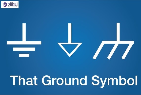
1. Earth Ground Symbol (⏚)
The earth ground symbol consists of three horizontal lines that get progressively shorter. It represents a connection to the physical earth, often used for safety and lightning protection in power systems.
2. Chassis Ground Symbol
This symbol resembles a horizontal line connected to a triangle with horizontal lines inside. It indicates a connection to the metal chassis of equipment, providing shielding and a common return path.
3. Signal Ground Symbol
Often shown as a downward-pointing triangle or a straight line with one horizontal line, this ground type serves as a reference point for low-voltage signals in sensitive electronics.
4. Protective Earth Symbol
A variation of the earth ground, sometimes displayed with an encircled cross or specific IEC symbol, indicating that the conductor is connected to safety earth.
Comparison Table
|
Symbol Type |
Appearance |
Main Use Case |
|
Earth Ground |
⏚ |
Safety, lightning protection |
|
Chassis Ground |
⏚ (variant with box) |
Shielding, equipment grounding |
|
Signal Ground |
▼ or horizontal line |
Low-voltage circuits, signal reference |
|
Protective Earth |
Encircled cross |
Personnel protectio |
How to Recognize Ground Symbols in Circuit Diagrams
Ground symbols are strategically placed throughout schematics to guide the reader on where the current returns or how the system stabilizes voltage levels. Here’s how to identify them effectively:
Visual Clues: Pay attention to the symbol’s shape and design. Each standard uses slightly different variations.
Positioning: Ground symbols often appear near power supplies, connectors, or points where multiple subsystems connect.
Contextual Reading: Consider the surrounding components; for instance, signal grounds are often near analog or digital ICs, while earth grounds are near power inputs.
Industry Standards for Ground Symbols
Different industries and regions use varying symbol standards. The most widely recognized standards include:
IEC (International Electrotechnical Commission)
IEC standards are widely adopted globally. They define specific shapes and annotations for each ground type. IEC 60617 is the most relevant standard for schematic symbols.
IEEE/ANSI (American National Standards Institute)
In the United States, ANSI Y32.2 (now IEEE 315) defines schematic symbols. While similar to IEC, subtle differences exist, particularly for protective earth and signal ground representations.
Key Differences
IEC symbols often focus more on graphical clarity.
ANSI symbols may include additional text annotations for clarity.
Always check the legend or documentation accompanying the schematic.
Practical Examples: Reading Real Circuit Diagrams
Power Supply Circuit
In a simple power supply schematic, you may see:
- Earth ground is connected to the AC input for safety.
- Chassis ground tied to the case or enclosure.
- Signal ground linked to low-voltage DC output circuits.
Mixed-Signal PCB
In mixed-signal designs:
- Digital ground (DGND) is isolated from analog ground (AGND) to reduce noise.
- Both grounds may merge at a single point, often the power source.
Automotive Wiring Diagram
In automotive systems:
- The chassis ground often connects directly to the vehicle body.
- Multiple grounding points ensure stable operation across subsystems like lights, sensors, and ECUs.
Troubleshooting: Common Ground Symbol Confusions
Even experienced engineers occasionally misread ground symbols, leading to design flaws or safety risks. Here are common pitfalls:
Chassis vs. Signal Ground: Confusing these can introduce noise or ground loops.
Multiple Ground Planes: Complex systems may require isolated grounds to prevent interference.
Symbol Variations: Some manufacturers use non-standard or outdated symbols. Always refer to the documentation.
Additional Tips for Beginners
To improve your circuit diagram reading skills:
Study Legends: Always review the schematic’s symbol legend or key.
Use Datasheets: Component datasheets often clarify grounding requirements.
Practice Reading: Download open-source schematics to practice identifying ground connections.
Follow Standards: Familiarize yourself with IEC 60617 and IEEE 315 standards.
Conclusion
Anyone who works with electronics must learn to read ground circuit symbols. Whether you are designing, repairing, or testing circuits, safety, usefulness and efficiency can be ensured by interpreting these symbols correctly. To develop into a great reader of circuit diagrams, maintain the character of evolving standards, and carry out endless practice with actual world schematics.
FAQ
Q1: What does a ground symbol mean in a circuit diagram?
A ground symbol indicates the reference point in the circuit's voltage system where current returns or stabilizes voltage levels.
Q2: Are there different types of ground symbols?
Yes. Some common ones are earth ground, chassis ground, signal ground and protective earth, with each having its purpose.
Q3: What standard defines ground symbols?
IEC 60617 and IEEE 315 (ANSI Y32.2) define ground circuit symbols used globally in electronics.
Q4: How do I know which ground symbol to use?
The choice depends on the circuit’s function: safety grounding uses earth ground, while signal processing circuits may use the signal ground.
Q5: What happens if I connect the wrong ground?
Incorrect grounding can cause noise, interference, malfunction, or safety hazards, especially in mixed-signal or high-power systems.
Related Articles
How to Reset Ground Fault Circuit Interrupter (GFCI) Safely
GND in Circuit: Working Principle, and Structure
Why Ground Fault Circuit Interrupter Keeps Tripping [Fix Guide]
Arc Fault vs Ground Fault Circuit Interrupter: Key Differences


