


What is Corner Reflector:Principle and Applications
A corner antenna, also known as a corner reflector, is an antenna designed to redirect incident electromagnetic signals generated from an external source. These antennas are particularly effective at higher microwave frequencies, making them a preferred choice for spacecraft antenna systems. Their popularity stems from their simple structure and lightweight construction, which are advantageous for space applications.
Corner antennas are constructed using various types of reflectors, including parabolic, ellipsoidal, hyperbolic, or spheroidal surfaces. They come in different configurations, such as plane, rod, corner, spherical, parabolic, and cylindrical variants.
This article offers a concise overview of corner reflector antennas, highlighting their functionality and applications.
A Corner Reflector Explained
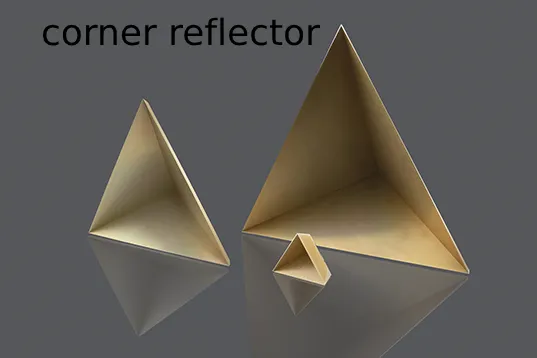
A corner reflector, a type of passive device, serves the purpose of redirecting radio signals back toward their emission source. This device, functioning as a retroreflector, comprises three flat surfaces intersecting at right angles, effectively reflecting waves directly back to the source, albeit altered in trajectory. Typically, these intersecting surfaces feature square shapes. Corner reflectors find extensive utility in radar system calibration.
Constructed from metal plates or wires arranged to form right angles, these reflectors possess the unique property of reflecting electromagnetic waves, rendering them conspicuous targets on radar displays even when located off-axis or at a distance. They serve as essential references or markers for radar measurements, facilitating assessments of speed, distance, position, or angle.
Corner reflectors manifest in various forms, notably Radar corner reflectors and optical corner reflectors. Radar corner reflectors consist of metals optimized for reflecting radio signals emitted by radar sets. In contrast, optical corner reflectors, also known as corner cubes or cube corners, employ three-sided glass prisms. These prisms are instrumental in laser ranging and surveying applications.
The Role of a Corner Reflector Explained
A corner reflector serves the purpose of amplifying radar echoes, especially from objects with inherently low effective Radar Cross-Section (RCS). This reflector typically comprises two or more electrically conductive surfaces arranged in a crossed configuration. Larger corner reflectors possess the capacity to reflect greater amounts of energy.
How Does a Corner Reflector Operate?
A corner reflector functions based on the principles of optics, whereby the reflected signal travels in a direction similar to its point of origin. Specifically, when an electromagnetic signal encounters a corner reflector, it undergoes reflection from each electrically conductive surface present. In essence, in a dihedral structure, the wave is reflected twice, while in a trihedral structure, it is reflected three times. Consequently, the propagation direction of the waves is reversed, reflecting them back toward their source. This mechanism renders the corner reflector a passive device.
Primarily utilized in antennas, reflectors are strategically positioned to enhance their directivity. Corner-shaped reflectors effectively confine radiated energy within the metallic plate, thereby improving directivity by reflecting energy in the desired direction.
Corner Reflector Antenna Overview
A corner reflector antenna represents a directional antenna primarily employed in UHF (Ultra High Frequency) and VHF (Very High Frequency) frequency ranges. Originally conceptualized by John D. Kraus in 1938, this antenna configuration features a dipole-driven element positioned in front of two flat rectangular reflecting surfaces, typically angled at 90 degrees to each other. Known for its moderate gain ranging from 10 to 15 dB, high front-to-back ratio spanning from 20 to 30 dB, and wide bandwidth characteristics, corner reflector antennas are valued for their performance.
Widely utilized in various applications, including UHF television point-to-point communication links, receiving antennas, data links for WANs (Wide Area Networks), and amateur radio antennas operating on bands such as 144 MHz, 420 MHz, and 1296 MHz, these antennas emit radio waves with linear polarization. Additionally, they offer the flexibility of mounting for either vertical or horizontal polarization, enhancing their versatility in diverse radio communication scenarios.
Types of Corner Reflectors Explained
There are two primary types of corner reflectors: dihedral and trihedral, each with distinct characteristics as outlined below.
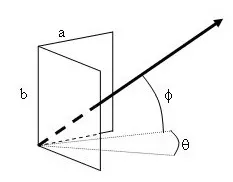
Dihedral Corner Reflector
A dihedral corner reflector is characterized by two surfaces arranged on orthogonal planes. Comprising two plane reflectors forming a 90-degree dihedral angle, this antenna configuration arises when two conducting sheets are joined perpendicularly. Predominantly employed in antennas, the dihedral corner reflector exhibits the property of returning waves to the emission source only when the incident beam direction aligns perpendicular to the intersection line of the planes. Wave reflection occurs twice within this type of reflector. However, due to their sensitivity to mechanical alignment, dihedral reflectors may encounter more operational challenges.
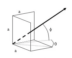
Trihedral Corner Reflector Overview
A trihedral corner reflector is distinguished by its configuration of three surfaces positioned on orthogonal planes. Constructed by connecting three conducting sheets in a perpendicular orientation, this type of corner reflector reflects waves three times. Typically employed in radar systems, trihedral corner reflectors play a crucial role in radar testing, data collection, and calibration processes.
One notable advantage of the trihedral corner reflector is its high tolerance to misalignment, facilitating rapid field setup and calibration procedures when necessary. When radio waves encounter this reflector, they strike the corner and undergo three successive reflections off each surface, resulting in an inverted wave directed back toward the emission source. Consequently, the trihedral reflector presents a prominent Radar Cross Section (RCS) target, making it ideal for radar system testing, data acquisition, and calibration in various applications.
These reflectors serve as canonical radar reflectors extensively utilized for calibrating and assessing the performance of radar systems. Renowned for their desirable attributes, they boast a sizable radar cross-section, facilitating accurate measurements across a broad spectrum of aspect angles. Moreover, their Theoretical RCS (Radar Cross Section) can be readily calculated based on the aspect angle, simplifying performance evaluation and calibration processes.
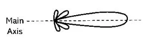
Corner Reflector Radiation Diagram
The vertical corner reflector's radiation pattern, illustrated in the accompanying figure, depicts the directional distribution of radio wave strength emanating from the antenna along its main axis. In the realm of antenna design, the radiation pattern serves as a graphical depiction of the antenna's far-field properties, showcasing the variation in radiated power as a function of distance from the antenna.
The corner reflector serves as a valuable tool for radar system calibration. Typically, this reflector comprises perpendicular plates intersecting each other. The two common types of corner reflectors are the trihedral and dihedral configurations.
In the case of the dihedral corner reflector, while it is sensitive to mechanical alignment, it exhibits high tolerance to misalignment. This feature facilitates swift field setup and calibration processes. The reflector consists simply of three right-angle plates, as depicted in the accompanying figure.
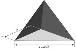
The effective cross-section of a trihedral reflector, denoted by Aeff, can be calculated using the formula:
\[ A_{eff} = \frac{a^2}{\sqrt{3}} \]
Where 'a' represents the side length of the trihedral reflector.
Furthermore, the radar cross-section (σ) can be determined by the equation:
\[ \sigma = \frac{4π a^4}{3λ^2} \]
Here, 'λ' signifies the wavelength of the radar signal.
In the trihedral corner reflector, incident waves strike the reflector's corner and undergo three successive reflections off each surface. As a result, the waves are redirected completely back toward the source, effectively providing an exceptionally high Radar Cross Section (RCS) target. This property makes the trihedral corner reflector invaluable for radar system testing and characterization purposes.
Advantages and Disadvantages Overview
Corner reflectors offer numerous advantages
1. Broadband Gain: At the lower end of the UHF band, corner reflectors provide expansive bandwidth gain.
2. High Gain: These reflectors boast high gain capabilities, enabling effective signal transmission and reception over long distances.
3. Strength in Numbers: Reflectors with multiple surfaces yield stronger reflections.
4. Suitability for Microwaves and UHF Frequencies: Ideal for microwaves and ultra-high frequencies where structures of one or two wavelengths in size are feasible.
5. Simplified Construction: Corner reflectors are straightforward to construct, deploy, and are cost-effective, often folding into portable units.
6. Self-Sufficiency: They operate without the need for external power sources, calibration, or ongoing maintenance.
7. Versatile Placement: These reflectors can be arranged in various orientations and locations to suit specific needs.
8. Target Replication: By altering their shape, number, and size, corner reflectors can mimic different types of targets such as vehicles, aircraft, or buildings.
9. Reliability in Radar Evaluation: Corner reflectors serve as dependable references for evaluating radar system performance.
10. Diagnostic Utility: They aid in assessing radar sensitivity, accuracy, and resolution, facilitating the identification and correction of biases or errors within radar systems.
However, it's important to note that while corner reflectors offer numerous advantages, they also have limitations that should be considered in specific applications.
Corner reflectors offer numerousoffer several advantages
1. Increased Bulk: Incorporating a corner reflector into the antenna setup can result in a bulky arrangement, potentially impacting portability and installation convenience.
2. Elevated Cost: The addition of a corner reflector increases the overall cost of the antenna system, potentially making it less economical compared to alternative configurations.
3. Limited Representativeness: Corner reflectors may not accurately replicate real-world radar targets, limiting their effectiveness in radar validation exercises.
4. Scenario Limitations: Reflectors used for radar validation may fail to encompass the full range of scenarios and challenges encountered by radar systems in practical settings.
5. Interference Concerns: Corner reflectors utilized for radar validation could interfere with other users or radar systems operating in the vicinity, potentially causing clutter, false alarms, or signal masking.
6. Regulatory Compliance Issues: Improper deployment of corner reflectors may lead to violations of airspace regulations or radar frequency band permissions, posing legal and operational risks.
It's essential to weigh these disadvantages against the specific requirements and constraints of each application when considering the use of corner reflectors in radar systems.
Applications of corner reflectors
Corner reflectors find diverse applications across various fields, including:
1. Radar Stealth: Utilized within radar systems, corner reflectors help obscure the presence of defense motor vehicles from adversaries' radar detection.
2. Television Signal Reception: Corner reflectors play a role in enhancing TV signal reception, commonly integrated into home antenna setups.
3. Optical Communication: These reflectors are extensively employed in optical communication applications, aiding in signal transmission and reception.
4. Radar Validation: When appropriately employed, corner reflectors serve as valuable tools for validating radar systems, ensuring accuracy and reliability in performance assessments.
5. Radio Frequency (RF) Applications: Widely utilized in UHF TV reception, wireless WAN data links, point-to-point communication links, and amateur radio antennas operating on bands such as 1296 MHz, 144 MHz, and 420 MHz.
6. Signal Reflection: Corner reflectors are employed to redirect radio waves or other electromagnetic signals back toward their emission source.
7. Radar Echo Enhancement: By generating strong radar echoes, corner reflectors facilitate the detection of objects with low effective Radar Cross-Section (RCS).
8. Security Reflectors: Corner reflectors serve as essential components in the manufacturing of security reflectors for bicycles, signs, and vehicles, enhancing visibility and safety.
9. Lunar Laser Ranging: These reflectors are utilized to bounce laser beams back toward Earth from the moon's surface, aiding in precise measurements and scientific research.
In conclusion
An antenna is a device designed to transmit or receive electromagnetic waves, typically used in communication systems to radiate electromagnetic signals into the surrounding space or to capture incoming signals. Antennas are essential components in various applications, including radio and television broadcasting, wireless communication, radar systems, satellite communication, and many others. They come in a variety of designs and configurations, each tailored to specific frequency ranges, signal characteristics, and application requirements. In essence, antennas serve as the interface between electronic devices and the electromagnetic spectrum, enabling the transmission and reception of signals for various communication purposes.
Related Articles
Basic Knowledge of Electronic Parts:Complete Guide


