


How to Wire a Trailer Light Connector: Pinout & Guide
Introduction to Trailer Light Connectors
Trailer lighting is not merely about convenience; it is also about safety as well as adherence to road rules. Be it the trailer of a boat, utility trailer, camper, or agricultural equipment, it is a legal requirement in most places to have operational trailer lights. A trailer light connector is an electrical connector that connects your towing vehicle with your trailer, and implements indicators of brake lights, turn signals, tail lights, and, in some instances, additional features such as reverse lights or electric brakes.
You will learn in this guide how to assemble a trailer light connector, learn different pinouts of a pin connector with 4, 5, 6 and 7 pin connectors, and get tips on troubleshooting and maintaining your trailer lighting system.
Types of Trailer Light Connectors
Different trailers require different levels of wiring depending on their features. Let’s explore the most common types of connectors:
Flat 4-Pin Connector
The most basic connector, used on small utility trailers.
Supports tail lights, left turn, right turn, and ground.
Ideal for light-duty towing without extra features.
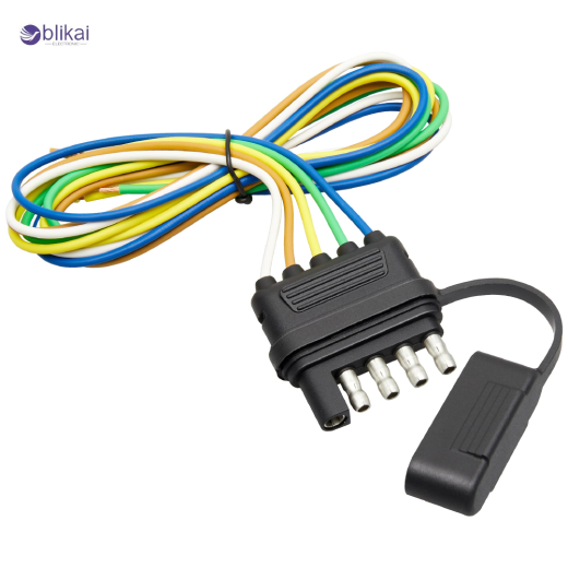
5-Pin Connector
Adds an extra wire compared to the 4-pin setup.
Commonly used for reverse lights or trailer brakes.
Found on boat trailers where backup lights are important.
6-Pin Round Connector
Applied in medium-duty trailers, horse trailers or campers.
Supplies brake light circuits, turn signals, ground, tail lights, electric brakes and auxiliary power.
7-Pin RV Blade Connector
The most versatile and heavy-duty option.
Found on RVs, travel trailers, and larger commercial trailers.
Supports all lighting functions, electric brakes, auxiliary power, and reverse lights.
Comparison Overview:
- 4-pin: Basic, lightweight trailers.
- 5-pin: Adds brake or reverse function.
- 6-pin: Medium trailers with extra features.
- 7-pin: Full-featured heavy trailers.
Trailer Light Connector Pinout Guide
Pinouts define which wire color connects to which trailer function. Standardized wiring helps avoid confusion when using adapters or replacing connectors.
Standard Color Coding for Trailer Wiring
While wire colors may vary by manufacturer, these are the common U.S. color codes:
- White: Ground
- Brown: Tail/running lights
- Green: Right turn signal & brake
- Yellow: Left turn signal & brake
- Blue: Electric brakes or auxiliary
- Red/Black: 12V battery or reverse lights
Pinout Tables for Different Connectors
4-Pin Trailer Connector Pinout
|
Pin |
Wire Color |
Function |
|
1 |
White |
Ground |
|
2 |
Brown |
Tail / Running Lights |
|
3 |
Green |
Right Turn / Brake |
|
4 |
Yellow |
Left Turn / Brake |
5-Pin Trailer Connector Pinout
|
Pin |
Wire Color |
Function |
|
1 |
White |
Ground |
|
2 |
Brown |
Tail / Running Lights |
|
3 |
Green |
Right Turn / Brake |
|
4 |
Yellow |
Left Turn / Brake |
|
5 |
Blue |
Reverse Lights / Brakes |
6-Pin Trailer Connector Pinout
|
Pin |
Wire Color |
Function |
|
1 |
White |
Ground |
|
2 |
Brown |
Tail / Running Lights |
|
3 |
Green |
Right Turn / Brake |
|
4 |
Yellow |
Left Turn / Brake |
|
5 |
Blue |
Electric Brakes |
|
6 |
Red/Black |
12V Power / Auxiliary |
7-Pin Trailer Connector Pinout
|
Pin |
Wire Color |
Function |
|
1 |
White |
Ground |
|
2 |
Brown |
Tail / Running Lights |
|
3 |
Green |
Right Turn / Brake |
|
4 |
Yellow |
Left Turn / Brake |
|
5 |
Blue |
Electric Brakes |
|
6 |
Red/Black |
12V Battery / Auxiliary |
|
7 |
Purple |
Reverse Lights |
Step-by-Step Guide to Wiring a Trailer Light Connector
A trailer connector can be wired, which can sound complex, but when done in a systematic procedure, it can be done.
Tools and Materials Required
- Wire stripper and cutter
- Crimping tool
- Electrical tape or heat shrink tubing
- Butt connectors or a soldering kit
- Trailer wiring harness
- Multimeter (for testing)
Step 1: Prepare the Trailer Wiring Harness
Find the wiring junction box or harness of the trailer.
Make sure that the wires are free and not corroded.
Step 2: Match Wire Colors to Functions
See the pinout tables of your connector.
Match each trailer wire to the vehicle wire.
Step 3: Strip and Connect Wires
Stripple off approximately 1/4 inch of insulation off each wire.
Inserting butt connectors or solder to make it permanent.
Step 4: Secure the Connections
Insulate with heat shrink tube or electrical tape.
Wind up the bundle wires so they do not become tangled.
Step 5: Mount the Connector
Connect the connector to the trailer tongue.
Make sure that it is not subject to road debris.
Step 6: Test the Trailer Lights
Join the trailer to the vehicle.
Turn signals, tail lights, and test brake lights.
Test your car out, and make sure everything is working properly.
Common Wiring Problems and Troubleshooting
Even with correct wiring, trailer lights can malfunction. Here’s how to diagnose and fix common issues:
Dim or Flickering Lights
Cause: Poor ground connection or corrosion.
Fix: Clean grounding points and tighten bolts.
One Side Not Working
Cause: Broken wire or loose connection.
Fix: Trace the wire using a Multimeter and reconnect.
All Lights Not Working
Cause: Blown fuse or disconnected harness.
Fix: Change the fuse and the vehicle-side connector.
Corrosion in the Connector
Cause: Exposure to moisture and salt.
Fix: Clean pins with electrical cleaner, and put dielectric grease on.
Miswired Pinout
Cause: This is due to improper mapping of the wires.
Fix: Recheck the pinout diagram and reconnect properly.
Safety Tips and Best Practices
- Double-check pinouts before finalizing connections.
- Use dielectric grease to prevent corrosion.
- Install cables in the frame of the trailer adequately.
- Attach clips on secure wires to prevent damage.
- Comply with local regulations on the necessary lights of trailers.
Applications of Trailer Light Connectors
A trailer light connector is needed in many applications in various types of vehicles and industries, and it guarantees the safety of towing and correct signaling on the road. They are versatile and can be used to address the requirements of recreational and commercial applications.
Utility Trailers: Utility trailers are usually trailers utilized to move materials, equipment or tools. Well-wired lights enhance visibility and safety since other road users can easily see the trailer when turning, braking and at night, driving.
Boat Trailers: boat trailers are often subjected to water and moisture and therefore corrosion-resistant or waterproof connectors are considered significant. These trailers also possess reverse lamp lights which assist them to dock and maneuver properly.
RVs and Campers: Recreational vehicles and campers commonly have complete 7-pin connectors to provide the additional functions like inside lights, electric brakes, and charge batteries when towing. Reliable connections are essential in preventing failures when travelling long distances.
Agricultural Trailers: These are more massive trailers and may have either a 6-pin or a 7-pin connection and optional circuits and support services (such as hydraulic pumps or night lights) fitted, which must be connected to the tractor.
Commercial Trailers: Commercial trailers, cargo trailers, and other large transport trailers need robust connectors to comply with the road safety rules. Effective lighting of trailers minimizes the risks of accidents and ensures adherence to the legal norms in case of transportation.
The appropriate connector of the trailer lights is not only safer but also less prone to problems in maintenance and guarantees reliability in the long term. Maintenance and correct installation methods are the key to maximum functionality and durability.
Conclusion
The concept of wiring a trailer light connector may appear complex, but with a little understanding of pinout, color-coding and assembly procedure, it is simple. Whether it is a basic 4-pin flat connector or a heavy duty 7-pin RV blade connector, the right wiring guide is sure to make you safe and reliable on the road.
The long life span of trailer lights requires regular inspection, grounding and preventing corrosion. This guide will help you wire your trailer connector without any trouble or pitfalls.
FAQs
What is the standard color code for trailer wiring?
They are most commonly white (ground), brown (tail lights), green (right turn), yellow (left turn), blue (brakes) and red/black (auxiliary or reverse).
How do I test if my trailer light connector is working?
When the turn signals, brakes or tail lights are on, test each pin using a multimeter or a trailer light tester.
Can I use a 4-pin to 7-pin adapter?
Adapters do work, though you do not get any additional functionality by not having the wiring in your trailer.
What gauge wire is best for trailer lights?
With most trailers, a 16-18 AWG is used in lights, and 12 -14 AWG is used in brakes and power circuits.
Why are my trailer lights not working even after wiring?
Most likely underlying causes are bad grounding, connector corrosion or a blown vehicle fuse.
Some images are sourced online. Please contact us for removal if any copyright concerns arise.


