


Rigid Flex PCB Guide: Structure, Components & Applications
What Is a Rigid Flex PCB?
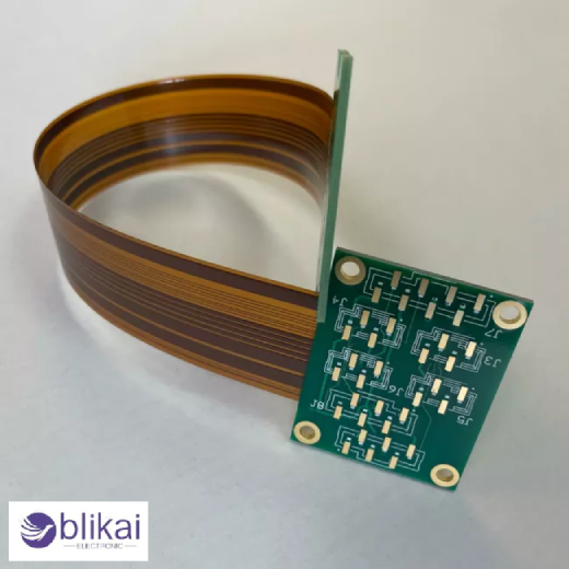
A rigid flex PCB is a printed circuit board that is a hybrid that incorporates rigid parts of PCB with flexible parts of PCB. In contrast to conventional rigid boards, which are based on connectors and cables, rigid flex PCBs permit electrical connection to pass through bendable flex layers. This design improves reliability, reduces interconnect failures, and enables compact electronic assemblies used in advanced electronic components and systems.
Basic Structure of a Rigid Flex PCB
A rigid flex PCB has a structure where the rigid parts act as the supports of the electronic components, and the flexible parts are able to bend or fold. The multilayer boards usually constitute the rigid areas, and the bendable layers, which interconnect them, are usually thin and flexible. These parts are permanently glued together, making one circuit that offers mechanical stability and flexibility.
Layer Stack-Up Configuration
Rigid flex PCBs require complex stack-ups consisting of signal layers, power planes and ground layers in both rigid and flexible areas. The flex layers are typically continuous through rigid areas, being electrically continuous. The stack-up design is important to control the impedance, signal-to-noise and mechanical durability.
Key Materials Used in Rigid Flex PCBs
FR-4 or high-Tg laminates are typically used in rigid sections, whereas polyimide substrates are used in flexible ones as a means of heat resistance and durability. The adhesiveless copper-clad laminates are normally selected in high-reliability designs. Material selection directly impacts thermal performance, flexibility, and electrical stability.
Copper Foil and Dielectric Materials
Copper foil thickness in rigid flex PCBs is carefully chosen to balance current capacity and flexibility. Rolled annealed copper is widely used in flex areas due to its superior bend endurance. Dielectric materials provide insulation while maintaining controlled impedance for high-speed electronic components.
Core Components on Rigid Flex PCBs
Rigid flex PCBs support a wide range of electronic components, including resistors, capacitors, inductors, integrated circuits, microcontrollers, sensors, and power devices. The majority of the components are mounted on the rigid parts with the flexible parts mostly used as interconnects between the rigid parts.
Connectors and Interconnect Reduction
Rigid flex PCBs also have the benefit of removing the use of traditional connectors and wiring harnesses. Flex layers built in board to board ensure reduction in signal loss, contact resistance as well as assembly complexity leading to a better system reliability.
How Rigid Flex PCBs Work
The operation of rigid flex PCBs involves passing electrical signals using copper continuous traces, which are passed across rigid and flexible parts. The flexible spaces absorb mechanical forces in motion or assembly, whereas the rigid spaces provide fixed mounting positions of delicate electronic parts.
Mechanical Flexibility and Stress Management
Proper bend radius design is essential to prevent copper cracking and dielectric failure. Stress relief techniques, such as staggered traces and curved routing, are used to extend the lifespan of flex regions subjected to repeated motion.
Electrical Performance and Signal Integrity
When designed appropriately, rigid flex PCBs can be used in high-speed and high-frequency applications. A controlled routing impedance, solid planes of ground, and smaller interconnect discontinuities all make controlled plans have superior signal integrity than cable-based designs.
Design Considerations for Rigid Flex PCBs
The process of designing rigid flex PCBs needs special consideration of bend points, layer transitions, as well as positioning of components. The components are to be stored in locations that are not related to bend lines, and stack-ups are to be symmetrical to prevent warping during fabrication.
Thermal Management in Rigid Flex Designs
The copper pours, heat sinks, and thermal vias are the main ways of heat dissipation. Flexible areas do not usually contain any heat-generating components, which means that they perform their work in a stable manner, and their service life is longer.
EMI and EMC Control
Compared to standard PCBs that have a series of connectors and long conduits, rigid flex PCBs have minimized electromagnetic interference. Ground planes, shielding strategies, and proper trace spacing help meet EMI and EMC compliance requirements in sensitive electronic systems.
Manufacturing Process of Rigid Flex PCBs
The production of the device is the process of laminating stiff and flexible stages and then drilling, plating, imaging, and etching. It is necessary to have precision alignment to make sure that layers continue through rigid-flex transitions.
Testing and Quality Inspection
Rigid flex PCBs are tested electrically, tested for impedance and tested for mechanical stress. Such inspections will guarantee the reliability of signals, their durability, and industry-friendly quality criteria.
Advantages and Disadvantages of Rigid Flex PCBs
Rigid flex PCB is space-saving, more reliable and easy to assemble. They are, however, costlier to design and produce compared to conventional PCB rigid boards, hence are only applicable in high-value or performance-based applications.
Typical Applications of Rigid Flex PCBs
Consumer Electronics and Wearable Devices
Rigid flex PCBs are widely used in smartphones, tablets, smartwatches, and wearable electronics, where compact size and lightweight design are critical. Designers can use their capability to bend and be integrated into small spaces to make devices thinner and, at the same time, offer reliable electrical connections between the closely spaced electronic parts.
Medical Devices and Healthcare Equipment
Rigid flex PCBs are used in medical electronics in imaging systems, patient monitoring equipment, implantable equipment, and diagnostic equipment. They have a high level of reliability, vibration resistance, and lower interconnect failure that can be used on applications where stability over time and high levels of safety are required.
Automotive Electronics Systems
Rigid flex PCBs are increasingly used in automotive electronics such as dashboard displays, camera modules, sensor systems, and advanced driver-assistance systems (ADAS). They are also resistant to vibration, variations in temperature and space that are common in contemporary cars.
Aerospace and Defense Applications
The aerospace and defense systems make use of the rigid flex PCBs in avionics, navigation systems, satellites and communication equipment. Mechanical strength combined with less weight is beneficial to maintain high performance and reliability in extreme working conditions.
Industrial Control and Automation Equipment
Rigid flex PCBs are utilized in robotic control, machine vision, and industrial sensors in industrial automation. They are designed to be integrated to enhance durability, ease of assembly, and ability to transmit signals in an electrically noisy industrial environment.
IoT and Compact Embedded Systems
Rigid flex PCBs are the best to be used in IoT devices and small embedded systems that need several electronic modules in a small area. They enable flexible mechanical layouts while maintaining consistent electrical performance across interconnected subsystems.
Rigid Flex PCB vs Traditional PCB Solutions
Rigid flex designs offer superior electrical performance, less weight than rigid PCBs and flex PCBs attached with cables and superior mechanical reliability. These would be good where space savings and life span are paramount.
Common Rigid Flex PCB Design Mistakes
Such problems as excessive bending, inappropriate material choice, and incorrect plan of layer stacking are typical. Such errors may create premature failure and high costs of production.
FAQs
Are rigid flex PCBs suitable for high-speed and high-frequency signals?
Yes, rigid flex PCBs are well-suited for high-speed and high-frequency signals. Continuous copper traces, controlled impedance stack-ups, and solid ground planes allow stable signal transmission with lower loss and fewer discontinuities than cable-connected PCB assemblies.
Why are rigid flex PCBs more expensive than standard PCBs?
The price of rigid flex PCBs is higher because of complicated materials, multifaceted stackups and unique manufacturing procedures. The increased initial cost is usually compensated by the fewer assembly processes, connectors, increased reliability and increased life cycle of the product.
When should you choose a rigid flex PCB instead of a rigid PCB?
A flex PCB with rigid flex is used in cases where there is a space constraint, reliability is an issue, or when mechanical movement is needed. They are ideal for compact electronics, foldable assemblies, and applications where connectors would reduce durability.
Some images are sourced online. Please contact us for removal if any copyright concerns arise.


