


Plug Flow Reactor (PFR): Principle,Features,and Applications
The plug flow phenomenon is a crucial attribute of these reactors, enabling molecules to enter and exit the reactor simultaneously, ensuring efficient reaction control for optimal reactant and product distribution. Hence, achieving optimal plug flow is essential for reactor performance. Reactors employing plug flow principles are commonly referred to as plug flow reactors or PFRs. The Plug Flow Reactor (PFR) represents a third general type of reactor, with nutrients continuously introduced into the reactor and moving through it as a "plug." This article provides an overview of plug flow reactor operation and its diverse applications.
.webp)
What is a Plug Flow Reactor?
A Plug Flow Reactor (PFR), also known as a piston flow reactor, represents an idealized rectangular flow reactor utilizing continuous fluid flow to process materials within a tube. It facilitates the depiction of chemical reactions in a cylindrical pipe, ensuring uniform distribution of reactants at consistent velocities along the flow direction without any mixing or backflow.
This reactor consists of a cylindrical pipe with openings at both ends for the inlet and outlet of reactants and products, respectively. To maintain uniform reaction conditions, water at a constant temperature is circulated through the reactor. Plug flow is achieved by continuously introducing materials at one end and removing them at the other. Commonly produced materials in PFRs include petrochemicals, polymers, and pharmaceuticals, among others. These reactors find extensive applications in both liquid and gas phase systems.
The plug flow reactor offers exceptional control over residence time and reaction conditions, leading to high conversion rates and suitability for reactions with high heat release or sensitivity to reactant concentrations. However, it has limitations due to the absence of radial mixing and only axial mixing.
Essential Characteristics
The essential characteristics of a plug flow reactor are as follows:
1. Direct Flow
In a PFR, both reactants and products move in one direction along the length of the reactor without any mixing back.
2. Gradual Change in Concentration
The concentration of reactants and products varies along the length of the reactor, while remaining constant across any vertical section perpendicular to the flow.
3. Residence Time
The time taken for a specific volume of reactant to pass through the PFR, known as residence time, remains consistent for all volumes.
Operating Principle of Plug Flow Reactor
The operation of a plug flow reactor involves the oxidation of alcohols and various organic compounds to yield refined chemicals such as pigments and dyes. Within this reactor, fluids move continuously and uniformly along a pipe or tube. Reactants are introduced at one end of the reactor, traverse the entire length, and exit at the opposite end.
The distinctive plug flow characteristic of this reactor ensures that all chemical reactants encounter identical conditions throughout the reactor's length, thus maintaining uniform residence times for each reactant. Consequently, a plug flow reactor is an optimal choice for primary reactions requiring precise control over residence time, temperature, and pressure.
Plug Flow Reactor Schematic
The configuration of a plug flow reactor can be achieved using a capillary, which is essentially a small tube or channel embedded within a plate. This constitutes a continuous reactor system, featuring an inlet for introducing reactants and an outlet for continuous discharge of reactor contents during operation.
A plug flow reactor (PFR) lacks an agitator and typically exhibits a cylindrical shape, facilitating fluid movement with minimal back mixing. Consequently, all fluid particles entering the reactor experience similar residence times. Conceptually, this reactor can be envisioned as a series of thin fluid layers, akin to tiny batch reactors, each thoroughly mixed within its respective layer to progress through the reactor like a piston.
An alternative formulation of the general mass balance equation for a single fluid slice within the reactor is as follows:
Inlet flow rate = Outlet flow rate + Consumption rate + Accumulation rate
Each component in the aforementioned expression is quantified in units of material flow rate, such as mol/sec.
Derivation of Plug Flow Reactor Equation
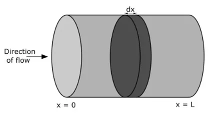
The plug-flow reactor represents an idealized system where every particle within a specific section exhibits uniform velocity and motion direction. Within a plug flow reactor (PFR), the absence of backflow or mixing results in fluid flow resembling a plug, moving continuously from the inlet to the outlet, as illustrated in the accompanying figure.
This reactor design is contingent upon the principles of mass and heat balance within a differential volume of fluid. Assuming isothermal conditions simplifies the analysis to focus solely on mass balance considerations.
Under the assumption of steady-state conditions, where reactant concentrations remain constant over time, the PFR typically operates. The mathematical expression for the PFR can be succinctly stated as:
udCi/dx = vir
Ci(0) = Ci(f)
0≤ x ≤ L
In the context where 'Ci' denotes reactant concentration, 'i' signifies concentration, 'u' represents fluid velocity, 'νi' stands for stoichiometric coefficient, 'r' represents reaction rate, and 'x' denotes the position within the reactor. Additionally, 'Caf' denotes the concentration of reactant A at the reactor inlet, and 'L' represents the length of the reactor. The fluid velocity 'u' is determined based on the volumetric flow rate 'Fv' (measured in m³/s) and the cross-sectional area 'S' of the reactor (measured in m²):
\[ u = \frac{Fv}{S} \]
In an ideal plug flow reactor (PFR), all liquid particles experience the same residence time within the reactor, referred to as the mean residence time, which can be calculated as:
\[ T = \frac{L}{u} \]
Here, 'T' represents the mean residence time, 'L' denotes the length of the reactor, and 'u' signifies the fluid velocity.
Residence time information is typically employed in chemical reactor engineering to forecast alterations in exit concentrations.
First-order Irreversible Reaction
Consider a straightforward decomposition reaction:
\[ A \rightarrow B \]
When the reaction is irreversible and follows first-order kinetics, the equation becomes:
\[ u\frac{dC_a}{dx} = -kC_a \]
Here, 'k' represents the kinetic constant, which typically relies on temperature. Often, an Arrhenius equation is employed to describe this temperature dependency. However, assuming isothermal conditions in this case negates the need for such considerations.
The solution for first-order irreversible reactions can be derived systematically, resulting in:
\[ C_a = C_{af} \exp \left( -\frac{xk}{u} \right) \]
Where:
- \( C_a \) denotes the concentration of 'A'.
- \( C_{af} \) represents the concentration of 'A' at the reactor inlet.
- 'x' stands for the position within the reactor.
- 'u' signifies the fluid velocity.
- 'k' signifies the kinetic constant.
Second-order Irreversible Reaction
Consider an example of a second-order irreversible reaction:
\[ 2A \rightarrow B \]
In the case of an irreversible second-order reaction, the equation becomes:
\[ u\frac{dC_a}{dx} = -2k(C_a)^2 \]
Here, 'k' represents the rate constant for the reaction.
Characteristics of Plug Flow Reactors
The key features of a plug flow reactor (PFR) are as follows:
1. Continuous Flow: Reactants flow continuously throughout the reactor in a unidirectional manner, with minimal mixing.
2. Reaction Progression: Reactions occur as reactants traverse the length of the reactor.
3. Changing Concentrations: Reactant concentrations vary along the reactor's length, with typically higher reaction rates observed at the inlet.
4. Applicability: PFRs are commonly employed for reactions requiring significant conversion and where reaction kinetics are unaffected by changes in concentration.
5. Short Residence Time: Residence time within the PFR is typically brief.
6. Biofilm Formation: In PFRs, biofilms can develop near the air-liquid interface, resembling environments like oral cavities or wet surfaces.
7. Biofilm Analysis: The biofilm produced in PFRs can be easily analyzed using various methods such as viable plate counts, thickness determination, and light microscopy.
8. Continuous Consumption: Reactants are continuously consumed as they flow along the reactor's length.
9. Structural Design: PFRs can be implemented as tubes packed with solid materials to facilitate reactions.
Advantages and Disadvantages
Advantages:
1. Compact Design: PFRs offer a smaller volume requirement for equivalent space-time and conversion levels compared to CSTRs (Continuous Stirred-Tank Reactors).
2. High Conversion Efficiency: They achieve higher conversion levels within the same reactor volume compared to CSTRs.
3. Gas-phase Catalytic Kinetics: PFRs are frequently utilized to determine gas-phase catalytic kinetics processes.
4. Effectiveness in Handling Reactions: PFRs exhibit superior performance in managing reactions, especially for a broad range of typical reactions, resulting in higher conversion rates per reactor volume compared to CSTRs.
5. Suitable for Quick Reactions: These reactors are well-suited for rapid reactions.
6. Efficient Heat Transfer: Heat transfer in PFRs can be effectively managed, making them an excellent choice for highly exothermic systems.
7. Consistent Residence Time: The plug flow nature ensures consistent residence time for all reactants, enhancing product quality by minimizing contamination formation and charring.
8. Easy Maintenance: PFRs have no moving parts, simplifying maintenance.
9. Mechanical Simplicity: PFRs are mechanically straightforward.
10. High Conversion Rate: They achieve high conversion rates per reactor volume.
11. Consistent Product Quality: Product quality remains unchanged due to the absence of back-mixing.
12. Suitable for Studying Quick Reactions: PFRs are excellent for studying fast reactions.
13. Efficient Utilization of Reactor Volume: They utilize reactor volume efficiently.
14. Suitable for Large Capacity Processes: PFRs excel in handling large capacity processes.
15. Low Pressure Drops: They experience fewer pressure drops.
16. Absence of Back-Mixing: PFRs eliminate back-mixing, ensuring direct scalability and efficient time control of residence and temperature.
Disadvantages:
1. Limited to Irreversible Reactions: PFRs are primarily suitable for irreversible reactions.
2. Sensitivity to Operating Conditions: Proper control of residence time, temperature, and mixing is crucial for optimal performance, and variations may affect outcomes.
3. Complex Modeling: Designing and modeling PFRs for complex reactions can be challenging.
4. Potential for Channeling: Non-ideal flow patterns can lead to channeling, impacting reaction efficiency.
5. Lack of Flexibility: PFRs may lack the flexibility to accommodate changes in reaction conditions or operating parameters.
6. Potential for Fouling: Fouling may occur due to the buildup of by-products or impurities in the reactor.
7. Limited Mixing: Mixing may be less efficient compared to other reactor types, affecting reaction kinetics.
8. Higher Capital Costs: Initial investment costs for PFRs may be higher compared to other reactor configurations.
9. Limited Turnaround Capability: PFRs may have limited flexibility for process changes or modifications.
Disadvantages of Plug Flow Reactors:
1. Temperature Control Challenges: Managing temperature within a PFR is challenging due to the wide range of temperature profiles, particularly in exothermic reactions.
2. Costly Maintenance: Maintenance and operational expenses for PFRs are comparatively high when compared to Continuous Stirred-Tank Reactors (CST).
3. Difficulty in Temperature Regulation: Temperature control poses difficulties in PFR operation.
4. Hot Spots: Exothermic reactions in PFRs may lead to the formation of hot spots, affecting reaction performance.
5. Control Complexity: Variations in composition and temperature make it challenging to control PFRs effectively.
6. Expensive Design and Maintenance: The complex design and assembly of PFRs contribute to higher costs associated with both their design and maintenance.
7. Limited Flexibility: PFRs are typically designed for specific reactions and may not easily accommodate changes in feedstocks or reaction conditions.
8. Maintenance and Cleaning Challenges: Narrow and elongated designs of PFRs make them difficult to maintain and clean.
9. Uneven Flow: Reactants may flow unevenly within PFRs, leading to the formation of hot spots or incomplete reactions.
10. Limited Applicability: Plug flow reactors may not be suitable for all applications, necessitating careful analysis of factors such as residence time, kinetics, and selectivity to determine the most appropriate reactor type for a given application.
Applications of Plug Flow Reactors:
1. Widely Employed in Various Industries: Plug flow reactors find common usage in fertilizer production, large-scale chemical manufacturing, petrochemical industries, and pharmaceutical production.
2. Polymerization Processes: They are extensively utilized in polymerization processes, including the production of polypropylene and polyethylene.
3. Liquid-Solid and Gas-Solid Reactions: Plug flow reactors are suitable for a diverse range of reaction systems, including both liquid-solid and gas-solid systems.
4. Heterogeneous and Homogeneous Reactions: They are suitable for both heterogeneous and homogeneous reactions, such as oil and fat hydrogenation.
5. Fine Chemical Production: PFRs are utilized for oxidizing alcohols and other organic compounds to produce fine chemicals like pigments and dyes.
In Summary
Therefore, this provides an overview of plug flow reactors, encompassing their operation, advantages, disadvantages, and applications. The design and selection of an optimal flow reactor remain a nuanced skill, honed over years of experience and knowledge accumulation. Additionally, plug flow reactors are sometimes referred to as continuous tubular reactors (CTR). In an idealized scenario, the reaction mixture's configuration resembles distinct plugs, each exhibiting uniform concentration. The concept assumes no axial mixing, thus eliminating back mixing within the reactor. Now, here's a question for you: What is a reactor?
Related Articles
What is an Integrated Circuit? Applications, Functions and Types (Guide)
Different Types of Battery Chargers: How Do They Differ?
Resistor Transistor Logic (RTL): Operation, Variations, Traits & Uses


