


Pull-Up and Pull-Down Resistors: Function, Application & Examples
What Are Pull-Up and Pull-Down Resistors?
Pull-up and pull-down resistors. These are resistors attached to a digital signal line to specify a default logic state in the absence of any active driving source. A pull-up resistor connects the signal line to a positive supply voltage (VCC), ensuring a default logic HIGH state, while a pull-down resistor connects the signal line to ground (GND), ensuring a default logic LOW state. These resistors are typically used on digital input pins, open-collector or open-drain outputs, and switch interfaces where the signal might otherwise be left electrically floating. Without a pull resistor, the input voltage can fluctuate unpredictably due to electrical noise, leakage currents, or electromagnetic interference, resulting in unstable logic behavior.
Why Floating Inputs Are a Problem
A floating input is an input to a digital device that has no connection to a specified source of voltage, so there is no specified voltage at that input. A small input voltage can cause the input voltage to vary between logic HIGH and logic LOW voltages due to even the smallest amounts of noise in CMOS logic, which has extremely high input impedance. It may cause false triggering, erratic behavior, more power consumption, and unpredictable system behavior. Floating inputs are especially problematic in microcontroller-based systems, where an uninitialized GPIO pin may randomly change state and cause unexpected interrupts, logic errors, or system instability. Pull-up and pull-down resistors solve this problem by gently biasing the input to a known voltage level.
How Pull-Up and Pull-Down Resistors Work
Pull-Up Resistor Working Principle
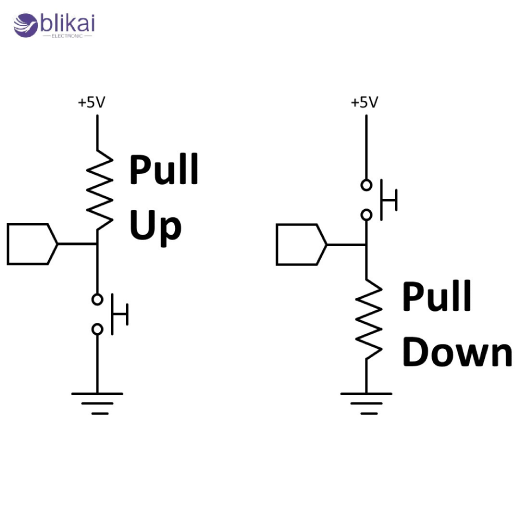
A pull-up resistor works by connecting a signal line to the positive supply voltage through a resistor, typically ranging from a few kilo-ohms to several tens of kilo-ohms. When no other component is actively driving the line, the resistor pulls the voltage up to VCC, representing a logic HIGH. When an external device, such as a switch or a transistor, pulls the line to ground, the resistor limits the current flow, preventing a short circuit and allowing the line to safely transition to a logic LOW. Such a setup is very common, as most digital systems, such as microcontrollers and communication buses, are not powered with current but sink much more efficiently.
Pull-Down Resistor Working Principle
A pull-down resistor works in reverse; that is, it ties the signal line to the ground via a resistor. When there is no active driving signal, the resistor is forced to ground the voltage to 0 V, giving a default logic LOW. When an external signal causes the line to go high, the resistor once again limits the current flow so that too much current is not conducted to the ground. Pull-down resistors are common in the system where the default LOW condition is desirable, or logic is to have an inactive signal at the LOW state instead of the HIGH condition.
Pull-Up vs Pull-Down Resistors
The pull-up and pull-down resistors are used to achieve the same fundamental purpose, but depending on the circuit requirements, their behaviour and application vary. Pull-up resistors are more commonly used in modern digital circuits because many ICs, microcontrollers, and communication protocols are optimized for active-low signaling and current sinking. Pull-down resistors, on the other hand, are still useful in certain logic families, power-up state control, and applications where a LOW default state is required. The choice between pull-up and pull-down depends on logic polarity, power consumption, noise immunity, and compatibility with connected devices.
Pull-Up vs Pull-Down vs Floating Input (Comparison Table)
|
Feature |
Pull-Up Resistor |
Pull-Down Resistor |
Floating Input |
|
Default Logic State |
HIGH (Logic 1) |
LOW (Logic 0) |
Undefined |
|
Connection |
Signal → Resistor → VCC |
Signal → Resistor → GND |
No defined connection |
|
Noise Immunity |
High |
High |
Very Poor |
|
Power Consumption |
Low (only when pulled LOW) |
Low (only when pulled HIGH) |
Unpredictable |
|
Typical Use Cases |
MCU inputs, I²C, buttons |
Logic control, enable pins |
Not recommended |
|
Reliability |
Stable and predictable |
Stable and predictable |
Unstable and unsafe |
Typical Pull-Up and Pull-Down Resistor Values
The most commonly used values of the pull-up and pull-down resistors are 100 kO and 1.0 kO, and the common value of 10 kO. The lower values of resistance provide a higher pull action and faster Signal switches at the cost of more current flowing during the switching of the line to the other condition. Greater resistance values minimise power usage at the cost of slower signal edges and greater noise sensitivity. The selection of the proper value of the resistor is based on power efficiency, speed of switching, noise resistance and the electrical properties of the devices that are being connected. In high-speed communication, it is often preferred to have lower values of resistance and low-power or low-varying input to have increased values of resistance.
Internal vs External Pull-Up and Pull-Down Resistors
Internal Pull-Up Resistors in Microcontrollers
Many modern microcontrollers, such as Arduino, ESP32, and STM32, include internal pull-up resistors that can be enabled through software configuration. These internalized pull-ups are easy to design and have a lower component count, so they are useful in prototyping and in low-cost applications. But internal pull-up resistors are usually of relatively high resistance, usually on the order of 20 kO and 50 kO, and this may not be sufficiently noisy immunity, especially in electrically noisy systems or in long cable runs.
External Pull-Up and Pull-Down Resistors
Externally provided pull-up and pull-down resistors provide more control over the value of resistance, power usage and signal characteristics. They are preferred in industrial, automotive, and high-reliability applications where precise electrical characteristics are required. External resistors are also uniform in comparing the performance of various models of microcontrollers, but internal pull-up values can significantly differ among and between microcontrollers and vendors.
Applications of Pull-Up and Pull-Down Resistors
Pull-Up and Pull-Down Resistors in Switch and Button Circuits
One of the most common applications of pull resistors is in push-button and switch circuits. A pull-up resistor combined with a normally open switch to ground ensures that the input reads HIGH when the button is not pressed and LOW when pressed. This is a simple, easy-to-use and common configuration used in embedded systems. It can also be used in pull-down configurations, which are not as popular in microcontroller-based designs.
Use in Microcontroller Digital Input Pins
Microcontroller GPIO pins configured as inputs require a defined logic level at all times. Pull-up and pull-down resistors prevent undefined states during power-up, reset, or idle conditions. They are especially important for interrupt pins, where a floating input could cause false interrupts and unintended code execution.
I²C, SPI, and Communication Interfaces
Communication protocols such as I²C rely heavily on pull-up resistors because they use open-drain or open-collector outputs. In I²C, pull-up resistors are mandatory to bring the SDA and SCL lines HIGH when no device is actively pulling them LOW. Without proper pull-up resistors, the bus would not function correctly, leading to communication errors and data corruption.
Pull-Up and Pull-Down Resistors in Logic ICs
Logic ICs, especially CMOS-based devices, often require pull resistors on unused or control pins to prevent floating inputs. Enable pins, reset lines, and mode selection pins commonly use pull-up or pull-down resistors to define a default operating state and ensure predictable behavior during power transitions.
Pull-Up and Pull-Down Resistor Circuit Examples
Basic Pull-Up Resistor Circuit Example
In a simple pull-up resistor circuit, the pull-up circuit line is connected to VCC using a resistor, and the pin is connected to ground using a switch. When the switch is off, the resistor draws the input HIGH. When the switch closes, his input is pulled to a LOW value, and current is conducted through the resistor to ground in a controlled fashion. This is very strong, simple and is commonly called upon in digital input circuits.
Basic Pull-Down Resistor Circuit Example
The circuit comprises a pull-down resistor circuit of the input pin to ground with a resistor and a switch or signal source to VCC. When the switch is in the open circuit, the resistor pulls the input to LOW. That is, when the switch is closed, the input is HIGH. The arrangement can be used in instances where the default LOW state is required. This arrangement is applicable in cases where a default LOW state is needed.
Microcontroller Input Example
In a microcontroller application, enabling an internal pull-up resistor allows a button to be connected directly between the input pin and ground, reducing external components. The firmware reads a logic HIGH when the button is released and a logic LOW when pressed, simplifying both hardware and software design.
Common Mistakes When Using Pull-Up and Pull-Down Resistors
A common mistake is omitting pull resistors entirely, resulting in floating inputs and unstable behavior. The other common mistake is taking resistor values that are either too large, so that there is poor noise immunity, or too small, so that they need not be run. In other cases, the designers may simply use the internal pull-up resistors they believe are not related to the environment, noise, the length of the cable, or the speed of the signal, and end up with a solution that is not reliable to work under the actual conditions.
Pull-Up and Pull-Down Resistors vs Other Input Conditioning Methods
While pull-up and pull-down resistors are sufficient for many applications, they are not always the best solution. In noisy environments or high-speed systems, Schmitt trigger inputs, buffers, or active signal conditioning may be required. Pull resistors provide a passive and cost-effective solution, but understanding their limitations is essential for robust circuit design.
FAQs
Why Are Pull-Up Resistors More Common Than Pull-Down?
Pull-up resistors are a more widespread choice since there are numerous digital systems that are designed to be efficient sinkers and employ active-low logic.
What Happens If I Don’t Use a Pull Resistor?
The input can be floating, resulting in random logic states, noise sensitivity, and unreliable system behavior.
Some images are sourced online. Please contact us for removal if any copyright concerns arise.


