


Transistor Series Voltage Regulator:All You Need to Know
Transistor Series Voltage Regulator
In a power supply system, a regulator is a crucial component used to control the output power in power electronics. Power electronics involves the control and conversion of electrical power within electronic systems. A voltage regulator ensures a stable output despite variations in input or load. Various types of voltage regulators include Zener, series, shunt, fixed positive, IC, adjustable, negative, dual tracking, and more. This article provides an overview of the transistor series voltage regulator.
What is a Transistor Series Voltage Regulator?
A series voltage regulator is characterized by certain limitations, such as high dissipation, lower efficiency, and sensitivity of the transistor and Zener diode voltages to temperature increases.
Circuit Design of Transistor Series Voltage Regulator
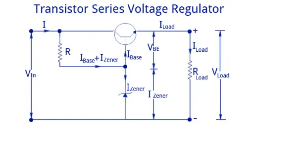
The design of a transistor series voltage regulator is illustrated below. This circuit comprises a transistor and a Zener diode. In this setup, the load current flows through the Q1 series transistor, hence the name "transistor series voltage regulator." When an unregulated DC supply is applied to the circuit's input terminals, a regulated output is obtained across the load. The Zener diode in this circuit provides the reference voltage.
Transistor Series Voltage Regulator
The operation of a transistor series voltage regulator relies on maintaining the transistor’s base voltage at a stable level set by the diode. For example, if the Zener voltage is 8V, the transistor’s base voltage will also be approximately 8V. Thus, the output voltage (Vout) can be calculated as Vout = VZ – VBE.
Operation
The operation of the Transistor Series Voltage Regulator can be understood in two scenarios: when the output voltage decreases and when it increases.
When the Output Voltage Decreases
If the output voltage decreases, the base-emitter (BE) voltage of the transistor increases, causing the transistor to conduct more. This increased conduction helps to stabilize the output voltage.
When the Output Voltage Increases
If the output voltage increases, the BE voltage of the transistor decreases, causing the transistor to conduct less. This decreased conduction helps to maintain the output voltage at a stable level.
Simple Emitter Follower Voltage Regulator
The electronic circuit design for a simple transistor emitter follower voltage regulator is quite straightforward. This type of circuit is not commonly used on its own in a linear power supply but may be employed within other equipment to step down voltage from a higher voltage rail.
This circuit utilizes a single pass transistor in an emitter follower configuration, along with a single Zener diode or another voltage regulator diode driven by a resistor from the unregulated supply.
This setup provides a simple feedback system to maintain the Zener voltage at the output, with a voltage reduction equal to the base-emitter junction voltage (0.6 volts for a silicon transistor).
Designing a series pass voltage regulator circuit like this is straightforward. By knowing the maximum current required by the load, one can calculate the maximum emitter current. This is done by dividing the load current (i.e., transistor emitter current) by the β or hfe of the transistor.
The Zener diode typically requires a minimum of around 10mA for a small Zener to maintain its regulated voltage. The resistor should be calculated to provide the base drive current and the minimum Zener current, based on the unregulated voltage, Zener voltage, and the required current: \((\text{Unregulated voltage} - \text{Zener voltage}) / \text{current}\).
It's important to add a small margin to the current calculation to ensure there is sufficient allowance for when the load, and consequently the transistor base, is drawing the full current.
The power dissipation capacity of the Zener diode should be calculated for the scenario when the load current, and thus the base current, is zero. In this case, the Zener diode must handle the full current passed by the series resistor.
Sometimes, a capacitor may be placed across the Zener diode or voltage reference diode to help eliminate noise and any voltage transients that may occur.
Integrated Circuit Linear Voltage Regulators
There is a wide selection of excellent integrated circuits that greatly simplify the design of a series regulator. Many of these ICs have been in use for numerous years, making them readily available and cost-effective.
Integrated circuits such as the well-known 78xx series, LM317, LM340 series, and others offer a simple yet effective solution for creating linear regulators.
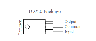
These ICs are typically three-terminal regulators, featuring one terminal for the input, one for the output, and a common terminal, which can be connected to ground or to a resistor network for voltage feedback.
78xx Series & LM340 Series Regulator Circuits
The 78xx series regulators have gained widespread popularity over the years and are offered in various voltage options, with the "xx" indicating the required voltage.
These regulators are straightforward three-terminal devices with numerous built-in features beyond voltage regulation, including internal current-limiting, thermal shutdown, and safe-area compensation, rendering them highly durable and almost indestructible.
This voltage regulator circuit is quite simple and requires only a few electronic components.
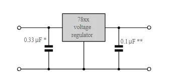
This is the fundamental circuit employed for any 7800 series voltage regulator. It is highly efficient and necessitates no additional components beyond those depicted for basic operation.
The LM340 series is essentially identical to the 78xx series, albeit with slightly higher specifications and closer tolerance on the output voltage.
LM317 Regulator Circuits
The LM317 voltage regulator IC is an adjustable 3-terminal positive voltage regulator capable of delivering over 1.5 A across an output voltage range of 1.2 V to 37 V.
This assumes that the input voltage allows for a sufficient voltage drop between the input and output to achieve adequate regulation at the desired output voltage.
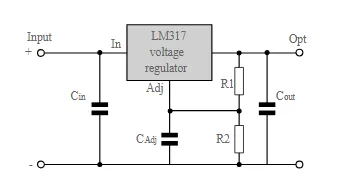
The LM317 serves as the essential electronic component for creating a straightforward yet effective variable voltage regulator circuit design. The design is straightforward, requiring only two external resistors to set the output voltage.
Furthermore, the IC features internal current limiting, thermal shutdown, and safe area compensation, enhancing its reliability and making it highly resilient to damage.
Due to the ability to set the output voltage using two external resistors, voltage regulator circuit designs can be configured to have programmable output regulation. Alternatively, by connecting a fixed resistor between the adjustment and output, the LM317 can function as a precision current regulator.
Low Dropout Series Voltage Regulators
One of the factors to consider with any regulator is the voltage required across the series pass element. Often, in linear regulators, a significant drop across this element is necessary to achieve optimal regulation and noise rejection. For instance, a linear regulator producing 12 volts output may require an input voltage of 18 volts or more.
Every linear regulator has a minimum voltage necessary across the series element before the regulator "drops out." This dropout voltage is a common feature in many linear regulator integrated circuits.
In certain circuits, having a low dropout regulator is crucial. If the available input voltage is not particularly high, having a low dropout linear regulator becomes essential. It must regulate effectively despite having a limited voltage across it.
Key Parameters for Series Linear Voltage Regulators
When examining the specifications for series linear regulators or designing an electronic circuit involving one, several parameters are of significant importance:
Maximum Input Voltage:
This denotes the highest input voltage the series regulator can tolerate. While a substantial voltage drop across the regulator enhances regulation, it's crucial not to exceed the maximum input voltage. It's generally advisable to operate at 60% or less of the specified maximum to enhance reliability.
Input Voltage-Output Voltage Differential:
This represents the maximum difference between the input and output voltages, which is crucial for determining the voltage across the series pass element. Paying heed to this parameter ensures greater reliability, especially if the regulator chip operates above ground.
Current Rating:
Every linear voltage regulator has a maximum current it can handle. The higher the current, the greater the power dissipation, particularly for large voltage drops across the series regulator element. The maximum current specification depends on various factors, including heat-sinking for the regulator element, ambient temperature, and the voltage differential.
Dropout Voltage:
This specification indicates the minimum input-output voltage differential across the series regulator for it to provide a regulated output. While for many regulators it can be several volts, for low dropout regulators, it can be as low as a few hundred millivolts.
Line Regulation:
Line regulation refers to the variation in output for a given change in the input voltage. To ensure good line regulation, there should be adequate voltage drop across the regulator and sufficient gain in the feedback and voltage sensing loop.
Load Regulation:
Load regulation denotes the variation in output voltage for a given change in the load or current drawn. Apart from good feedback in the voltage sense loop, the current-carrying wires should also be capable of carrying the current without significant voltage drop. Some electronic circuit designs may sense the voltage directly at the load to mitigate the effects of voltage drop along the wires. Additionally, ensuring that the regulator's supply can handle the required current levels is essential.
Advantages and Disadvantages
Advantages of the Transistor Series Voltage Regulator
- The primary advantage of this voltage regulator circuit is that changes in the Zener current are reduced by a factor of ‘ß’. As a result, the Zener impedance effect is significantly minimized, providing a more stabilized output.
Disadvantages of the Transistor Series Voltage Regulator
- Although changes in the Zener current are greatly reduced, the output is not entirely stable. This instability occurs because both the Zener voltage (VZ) and the base-emitter voltage (VBE) decrease as the room temperature rises.
- Adjusting the output voltage is challenging because the circuit does not provide any mechanisms for easy modifications.
Thus, the efficiency of a Zener regulated power supply (RPS) becomes extremely low when the load current is high. Under these conditions, a transistor-based Zener-controlled regulator is often used to maintain a stable output voltage. Fundamentally, transistor voltage regulators controlled by Zener diodes are classified into two types: series voltage regulators and shunt voltage regulators. Here is a question for you: What is the main function of a voltage regulator?


