


What is a Bypass Capacitor & Why Do You Need One?
Have you ever noticed weird noises in your electronic circuits or questioned why the well-kept system does not perform as per your expectations? Power supply fluctuations may well be the nasty hidden gremlins buffeting your projects, surfacing from causing small hiccups to full system crash-downs.
Understanding Bypass Capacitors
Bypass capacitors, or decoupling capacitors, are electronic circuit components that are used to maintain stable voltage and suppress noise. Often small devices, and becoming further down in capacitance value, the capacitor provides a local energy storage function to quickly provide a current need for some circuits or components. Their primary function is to "bypass" high-frequency noise and sudden voltage fluctuations to ground, ensuring a clean and steady power supply for sensitive electronic parts.
Types of Bypass Capacitors
- There are several types of bypass capacitors, each suited for different applications:
- Ceramic capacitors: Most common due to their low cost and small size
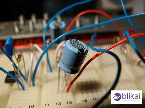
- Electrolytic capacitors: Offer higher capacitance values but are physically larger
- Tantalum capacitors: Provide excellent stability and reliability in compact sizes
- Film capacitors: Known for their low noise characteristics and high voltage ratings
How Bypass Capacitors Work
Bypass capacitors work by exploiting their ability to store and release electrical charge quickly. When a sudden demand for current occurs in a circuit, the bypass capacitor can supply this energy faster than the main power source. This rapid response helps maintain a stable voltage level and prevents voltage drops that could affect circuit performance.
Bypass capacitors act as low-impedance paths for high-frequency signals and short unwanted signals to ground, thereby preventing interference with the proper operation of sensitive components. This noise-filtering action is crucial in digital circuits, where clean power supplies are essential for accurate signal processing.
Common Applications of Bypass Capacitors
A. Digital circuits
The bypass capacitors maintain the integrity of the signals and help to minimize the noise in digital circuits. These bypass caps are essentially located very close to the power supply pins of ICs and provide a local charge source. This helps to suppress high-frequency noise and voltage spikes that can occur during rapid switching of digital signals. By doing so, bypass capacitors ensure stable operation of logic gates, microprocessors, and other digital components.
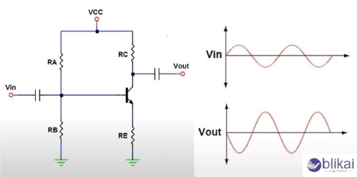
B. Analog circuits
Bypass capacitors tremendously help to provide stable voltage supplies to analog circuits and are also important in filtering noise. Power line bypass capacitors will filter high-frequency noise from power supply by operational amplifiers and other analog ICs so that there is more accurate processing of the signal involved. They also present a great way of instability and suppression of oscillations, thus improving the circuit's stability-a fact that is most critical in analog applications with precision, audio systems, and sensor interfaces.
C. Mixed-signal systems
Mixed-signal systems contain both analog and digital components and, therefore, largely on bypass capacitors for the integrity of signals. These capacitors are effective in decoupling the analog and digital portions of a circuit, shielding sensitive analog signals from the onslaught of digital noise. This is especially crucial where data converters (ADCs and DACs) are concerned, as noise would heavily compromise purity and the associated accuracy of conversion.
D. Power supply decoupling
Among pernicious applications of bypass capacitors is power supply decoupling, placing these components near the power inputs of ICs and other components. This minimizes ripple on the power supply voltage and provides a stable power supply. This is even more critical for complex systems with multiple voltage domains or inclusion of switching power supplies capable of generating some noise.
E. RF and high-frequency circuits
Bypass capacitors are employed in RF and high-frequency circuits for the sake of maintaining signal integrity and minimizing unwanted coupling between different stages of a circuit. Bypass capacitors help to provide a low-impedance path to ground for high-frequency noise thereby reducing electromagnetic interference (EMI) and boosting general circuit performance. This is even more applicable to wireless communication systems in which signal quality is necessary for maintaining high data rates and long-range of communication.
Selecting the Right Bypass Capacitor
Capacitance value considerations
The capacitance value is very important when a capacitor is being selected for bypassing. The generally used value \(0.1-10µF; the range differs according to the application. In digital circuits, a 0.1µF is quite enough while in analog circuits the required would be higher than this. One needs to analyze the frequency of the noise that needs to be suppressed and the impedance of the power supply. A good rule of thumb is to pick the capacitance that shall provide low impedance at the frequency of interest.
Voltage rating requirements
Bypass capacitors should have a voltage rating much higher than the maximum voltage that will appear in the circuit. It is wise to leave at least a 25% margin for voltage spikes. For example, in a circuit operating at 5V, the capacitor should be rated for at least 6.25V. Keep in mind to consider the DC bias when selecting voltage ratings, as ceramic capacitors may lose capacitance.
Frequency response characteristics
Bypass capacitors should have low equivalent series resistance and low equivalent series inductance to remove the high-frequency noise. Ceramic capacitors are generally the first choice because of their superior performance at high frequencies. For broader frequency coverage, consider using multiple capacitors in parallel, each targeting a different frequency range.
Physical size and package options
The physical size of the bypass capacitor affects its performance and placement. Smaller packages (e.g., 0402, 0603) have lower parasitic inductance, making them better for high-frequency applications. However, they also have lower capacitance values. Larger packages can provide higher capacitance but may introduce more parasitic effects. Consider the available space on your PCB and the required capacitance when choosing the package size.
Proper Installation and Placement
Optimal positioning on PCB
When installing bypass capacitors, optimal positioning on the PCB is crucial for effective noise suppression. These capacitors should be as close to the power pins of the IC they support as possible. The smaller the loop area between the capacitor and IC, the less parasitic inductance involved and thus the better the high-frequency performance.
Minimizing lead length
The length of the traces connecting the bypass capacitor to the IC's power and ground pins should be kept as short as possible. Longer leads introduce unwanted inductance, which can diminish the capacitor's effectiveness at higher frequencies. Use wide, short traces to minimize resistance and inductance, ensuring the capacitor can respond quickly to sudden current demands.
Grounding considerations
Proper grounding is essential for bypass capacitors to function effectively. Connect the capacitor's ground terminal directly to the ground plane using a via placed as close to the capacitor as possible. This technique reduces the ground return path impedance, enhancing the capacitor's ability to shunt high-frequency noise to ground.
Troubleshooting with Bypass Capacitors
Identifying noise-related issues
In troubleshooting sets of electronic circuits, noise-related issues manifest as unwanted fluctuation in voltage or current. Such disruptions can be harmful to the circuit performance-if not produce system failure. Hence, when dealing with noise-related problems, keep your sights peeled for intermittent operation, unexpected signal distortions, or unexplained voltage drops. Use an oscilloscope to visualize the noise on power supply lines or sensitive signal paths. Pay close attention to high-frequency oscillations or sudden spikes that could indicate inadequate bypass capacitor performance.
Testing and measuring capacitor performance
To check the bypass capacitor performance, some special test equipment would be required, like an impedance analyzer or LCR meter. Such equipment would measure various properties, including the actual capacitance value, equivalent series resistance (ESR), and resonant frequency. Any discrepancies between the measurements and the manufacturer's specifications need to be checked. A high-frequency oscilloscope can test the capacitor's ability to filter transients and to keep the DC voltage stable while in operation. Look for minimal voltage ripple and quick response to load changes as indicators of proper bypass capacitor function.
Replacing faulty bypass capacitors
After the faulty bypass capacitor has been identified, it should be replaced immediately with its equivalent or a better component. Ensure that the replacement capacitor has an equally or better capacitance value, voltage rating, and temperature characteristics. The new capacitor must be fitted with the shortest leads and the right way around to optimize its filtering performance. After replacing the capacitor, the circuit should be bent to check if its performance has improved and if the noise levels have been lowered. It is particularly worth mentioning that sometimes higher quality capacitors or combinations of several capacitors in parallel lead to noise suppression and improve overall system stability.
Conclusion
Bypass capacitors are, in short, an important part of the electronic circuits because it is the military against unwanted and unfriendly noise intrusion and fluctuation of voltage. Used in practically every application, such as power supply smoothing and protection of highly sensitive components, these tiny and robust components essentially serve to improve the integrity of a signal and enhance circuit performance.
Related Articles
How to Install a Capacitor to Two Amps
Radial vs Axial Capacitor: Whats the Differences?


