


Flexible Alternating Current Transmission System:Working and Types
A Flexible Alternating Current Transmission System (FACTS) comprises a group of power-electronic devices intended for application on an AC transmission system to enhance and regulate power flow and voltage support. FACTS devices serve as alternative solutions to traditional electric grid enhancements, particularly in scenarios where constructing additional transmission lines or substations is not feasible economically or logistically.
 (1).webp)
Generally, FACTS devices improve power and voltage in three primary ways: by providing shunt compensation for voltage (replacing the role of capacitors or inductors), series compensation for impedance (substituting series capacitors), or phase-angle compensation (replacing generator droop control or phase-shifting transformers). While traditional equipment can achieve these functions, FACTS devices utilize power electronics that switch rapidly, operating within sub-cycles rather than over seconds or minutes. Most FACTS devices are dynamic, capable of adjusting voltage across a range rather than just on or off, and are multi-quadrant, meaning they can both supply and absorb reactive power, and sometimes real power as well. These characteristics define their "flexible" nature, making them well-suited for applications with variable or evolving requirements.
The FACTs family originated from advancements in High-Voltage Direct-Current (HVDC) conversion and transmission, where Power Electronics were employed to convert AC to DC for facilitating substantial, manageable power transfers.[1] While HVDC concentrated on AC to DC conversion, FACTs devices utilized these technological developments to regulate power and voltage within the AC transmission system. The Static VAR Compensator (SVC) stands out as the most prevalent type of FACTs device, employing Thyristors to switch and manage shunt capacitors and reactors, respectively.
Synchronous Machines were commonly used at that time as generators and could provide some reactive power support; however, their effectiveness was limited by increased losses. As higher voltage transmission lines extended loads farther from sources, their efficiency decreased. To address this, fixed shunt capacitor and reactor banks were deployed strategically. Shunt capacitors, switched by circuit breakers, effectively managed varying reactive power demands caused by fluctuating loads.[3] Nonetheless, this approach had its constraints.
Shunt capacitors and reactors are fixed devices, capable only of being toggled on or off. This necessitated precise sizing studies[4] or acceptance of less than optimal effects on transmission line voltages. Recognizing the need for a more dynamic and adaptable solution, the mercury-arc valve emerged in the early 20th century. Similar to vacuum tubes, mercury-arc valves were high-powered rectifiers capable of converting high AC voltages to DC. Advancements in technology eventually enabled them to invert power as well, finding application in power systems and HVDC connections. When paired with reactors, different switching patterns could vary the effective connected inductance,[5] allowing for more dynamic control. Arc valves remained prominent in power electronics until the advent of solid-state semiconductors in the mid-20th century.
With the advent of semiconductors replacing vacuum tubes, the thyristor revolutionized the development of the first modern FACTs devices, such as the Static VAR Compensator (SVC). Functioning akin to a circuit breaker capable of rapid millisecond switching, it facilitated quick activation of capacitor banks. When coupled with a reactor and switched at sub-cycle intervals, it enabled adjustable effective inductance. Moreover, the thyristor significantly enhanced control systems, enabling SVCs to swiftly detect and respond to faults for better system support.[8] The dominance of the thyristor persisted in the FACTs and HVDC domains until the late 20th century, when IGBTs began to match its power ratings.
Theory
The fundamental theory governing how FACTs devices impact the AC transmission system revolves around analyzing power transfer between two points within the AC grid. This analysis is crucial for understanding the operational dynamics of an AC electrical grid, which comprises multiple nodes (substations) sometimes lacking in sources (generators) or loads. It is essential to calculate and manage power flow at each node (substation bus) to ensure that the grid's design and topology do not impede the delivery of generated electricity to loads.This becomes particularly critical as Transmission Lines extend over distances ranging from dozens to hundreds of miles, introducing significant impedance and voltage drops into the system.
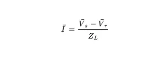
When considering two buses, each characterized by its voltage magnitude and phase angle, connected by a Transmission Line with a specific impedance, the current flowing between them can be expressed as
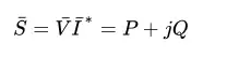
Apparent power flow, and consequently real and reactive power, is determined by
Combining these two equations yields the real and reactive power flow as dependent on voltages and impedance. This process is relatively straightforward and is performed in load-flow and power analysis software, but the resulting equations can be complex to interpret intuitively. To simplify, two approximations are commonly applied: assuming a lossless Transmission Line (reasonable with the use of very low resistance conductors) and disregarding capacitance on the line (typically fair for 200kV lines and below). This simplification reduces the line impedance to purely reactance, resulting in the real and reactive power as
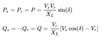
where
\( V_{s} \) is the magnitude of the Sending-End Voltage at the first bus,
\( V_{r} \) is the magnitude of the Receiving-End Voltage at the second bus,
\( X_{L} \) is the reactance of the Transmission Line between the buses,
\( \delta \) is the phase angle difference between the sending-end and receiving-end voltages.
From these equations, it is evident that three variables influence real and reactive power flow on a Transmission Line: the voltage magnitudes at each bus, the line reactance between them, and the phase angle difference between their voltages. All FACTs devices operate on the fundamental principle that modifying one or more of these variables will alter the real and reactive power flow on the transmission line. Some FACTs devices adjust a single variable, while others manage all three.
It is important to note, as will be elaborated below, that FACTs devices do not generate or add real power to the system; rather, they modify the circuit parameters between two points to influence the timing and manner of power flow.
Types of FACTs Devices
Since FACTs devices can modify up to three parameters—voltage, impedance, and/or phase angle—they are typically classified based on the parameter they primarily control. Given the prevalence of traditional devices for voltage (such as shunt capacitors and reactors) and impedance control (like series capacitors and load-flow reactors), FACTs devices targeting these parameters are categorized as shunt and series devices, respectively.
Shunt Compensation Devices
Shunt compensation aims to enhance voltage and facilitate increased power flow by connecting a device in parallel with the system. This function is conventionally fulfilled by using shunt capacitors and inductors (reactors), akin to Power Factor Correction.
The most commonly used shunt compensation device is the Static VAR Compensator (SVC). SVCs employ power electronics, typically Thyristors, to switch fixed capacitors and reactors. These configurations are known as Thyristor Switched Capacitor (TSC) and Thyristor Switched Reactor (TSR), respectively. Thyristors are capable of sub-cycle switching, enabling precise control over reactive power generation by the reactor. When operated in this manner, the TSR is referred to as a Thyristor Controlled Reactor (TCR). TCRs generate significant harmonics and necessitate Filter Banks to mitigate adverse effects on the system.
Another form of shunt compensation is the Static Synchronous Compensator (STATCOM). Power electronics are integrated with a reactor to form a Voltage-Sourced Converter (VSC), which, when connected to an AC system, constitutes a STATCOM. VSCs operate on the principle of measuring the system voltage to adjust the voltage of the power electronics, thereby controlling the flow of reactive power into or out of the STATCOM. Early STATCOMs utilized thyristors for power electronics and Pulse-Width Modulation (PWM) for reactive power control. However, advancements in semiconductor technology have led to the adoption of Insulated-Gate Bipolar Transistors (IGBTs) as replacements.
Series Compensation Devices
Series compensation devices alter the impedance of the Transmission Line to either increase or decrease power flow. Power flow is augmented by introducing a series capacitor to counteract line inductance, or reduced by incorporating a series load-flow reactor to supplement line inductance.
One form of series compensation is the Thyristor-Controlled Series Capacitor (TCSC), which integrates a TCR from an SVC in parallel with a conventional fixed series capacitor. Due to concerns about stored charge making it impractical to switch capacitors at sub-cycle intervals using power electronics, a TCR is utilized to adjust inductance dynamically, thereby offsetting the capacitor. This setup allows for dynamic adjustment of power flow on a transmission line.
A VSC can also serve as a series compensation device when connected across the secondary winding of a series-connected transformer. This configuration is known as a Static Synchronous Series Compensator (SSSC), offering advantages such as smaller reactor size compared to a TCSC, and reduced harmonic generation characteristic of a VSC (or Voltage-Source Inverter - VSI when employed in an SSSC), in contrast to a TCR.
Phase Angle Compensation
Power transmission between two points within an AC system occurs only when there is a phase angle disparity between the buses. Traditionally managed by generators, this method becomes less effective in large grids for regulating power flow across distant buses. Phase-Shifting Transformers (PST) are commonly employed in such scenarios, serving either as a Phase-Angle Regulator (PAR) or controlling both phase angle and voltage.
A straightforward approach to phase angle compensation involves replacing the tap changer on a PAR with thyristors to selectively switch parts of the winding in and out, creating a Thyristor-Controlled Phase-Shifting Transformer (TCPST).However, this is typically avoided due to the higher cost compared to a conventional PAR. Instead, the concept is expanded by replacing a Quadrature Booster with a device known as a Thyristor-Controlled Phase-Angle Regulator (TCPAR), also referred to as a Static Phase-Shifter (SPS). A TCPAR essentially replaces the mechanical components of the exciter and booster transformers with power electronics, usually thyristors, as shown in the schematic.
Another method to implement a TCPAR involves separating the exciter and booster transformers and controlling their secondaries with distinct sets of power electronics. These sets are interconnected via a DC bus, often using GTO thyristors or IGBTs, to form a TCPAR. While this approach may seem initially complex, it mirrors the separate control of shunt and series transformers and their electronics. Notably, the shunt section functions similarly to a STATCOM, while the series section operates akin to a Static Synchronous Series Compensator (SSSC). With power supplied from the shunt section via the DC bus to the series section, the device acts as a Phase-Angle Regulator. The isolation provided by the DC bus enables independent control of the shunt voltage by the STATCOM or the line impedance by the SSSC. This integrated capability gives rise to the Unified Power Flow Controller (UPFC), capable of managing all three parameters influencing power flow control.
Related Articles
Comparative Analysis of DC Transmission and AC Power
Impact of IRF3205 MOSFET on Power Electronics: Advancements and Applications
Thyristor vs Transistor: What are the Differences?
The Interconnection Between Semiconductors and Cybersecurity


